
Specifications
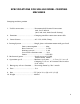
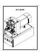
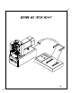
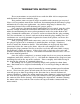
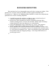
Table Of Contents
- SPA-100 Manual Cover Sheet
- Machine Introduction
- Specifications
- Manual Page
- Diagrams
- Basic Machine Diagram
- Machine and Tester Set-Up
- Machine and Guard Assembly
- Machine Base and Panels Assembly
- Motor and Tool Slide Assembly
- Tool Slide and Punch Holders
- Ram Slide Assembly
- Nest Assembly
- Nest Block Including Nests
- Micro Switch and Nest Stop Assembly
- Punch Holder Assembly (8 Position)
- Cam and Adjustment Assembly
- Test Assembly
- Test Block Assembly - Micro Switch Asseembly
- Controller and Circuits
- Termination Instructions
- Receiving Inspection
- Recommended Spare Tooling and Troubleshooting Tips
- Maintenance for SPA-100
- SPA-100 Parts List
SPECIFICATIONS FOR SPA-100 MODEL CRIMPING
MACHINES
Crimping machine portion
1. Usable connectors…………………Recommended Sentinel Connectors
8x8, Cat 5 &Cat 6
(4x4, 2x6, 4x6, 6x6 Consult factory)
2. Function ………………………….. Crimping modular connectors onto cable
3. Power Source ……………………. AC 115v, 60Hz, 5Amp
4. Driving System …………………… Single phase induction motor with gear head
Power consumption …………… 90w
Rated current ………………….. 0.75A
Starting current ……………….. 1.9A
Gear head reduction ratio …… 30:1
Power………………………………1/10 H.P.
5. Mechanical power ……………….. Punch pressure 130Kg
Punch stroke 16mm
6. Operation speed …………………. Machine cycle time …… 1.5 sec. (1.1 sec. of
Crimping + 0.5 sec. of electrical check under
10 ft. cable)
7. Emergency release function ……Reversing motor by “Rev” switch
8. Fuse ………………………………… 5 A
9. Size ……………………………….. 5.5” (w) x 10 5/8 (h) x 13 1/8 (d)
10. Weight ……………………………. 40.4lbs
2