
User manual


2.2. Site Considerations
The CC121 is designed to be used either in a 19-inch instrument rack or in a bench-top configuration. It is delivered
in the bench-top configuration with four feet screwed into the holes provided on the bottom of the crate.
NOTE : With the feet in the bench-top configuration, the crate height is slightly more than the standard 9U . In
order to use the crate in a 19-inch instrument rack, the user must unscrew the feet and, to avoid losing
them, screw them back into the stocking holes provided in the lower part of the rear panel.
CAUTION : Keep other equipment a minimum of 75mm (3in.) away from the air inlets and outlets.
2.3. AC Mains Power
2.3.1. Connecting to AC Mains Power
CAUTION : Make sure that the main power switch is in the 0 position (OFF) before connecting the power cord
to AC mains power.
The power supply is universal, which means that the crate can connect to all standard worldwide input voltages.
Attach input power through the rear panel AC Line inlet using the appropriate power cord supplied. Refer to the
paragraph 1.7. Packaging and Handling for the power cord specification.
2.3.2. Fuses
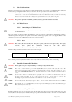
WARNING : The value of the F1 and F2 power line fuses depend of the AC power input voltage. For safety
reasons, please follow the instructions shown in the table below.
Disconnect the power cord before replacing the fuses.
The F1 and F2 power-line fuse-holders are located on the rear panel.
85 – 132 VAC
5x20mm slow-blow fuse: T 16A H 250V Acqiris PN: EF011160A
190 – 264 VAC
5x20mm slow-blow fuse: T 8A H 250V Acqiris PN: EF010800A
For continued protection against fire hazard, replace only with a fuse of the same type and correct rating.
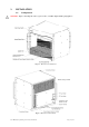
2.4. Installing CompactPCI Modules
CAUTION : Turn off the crate power before installing or removing CompactPCI modules.
NOTE : The crate controller must be placed in the System Slot (slot 1) located at the left of the crate. The
System Slot is identified with the number 1 surrounded with a triangle. All other modules are to be
placed in the Peripheral Slots that are identified with their respective number surrounded with a
circle.
NOTE : If you want the driver to automatically recognize the crate as a CC121 you should put at least one
Acqiris acquisition module into one of the last 7 slots. If you do not do this, you can use the
GeoMapper application discussed in the User Manual to create an AqGeo.map file.
NOTE : If you want to chain other CC121 crates to this one, please put the additional Acqiris ICxxx or MXI-3
PXI8335 modules in slots 2-4 of this upstream crate.
NOTE : The CC121 crate accepts PXI modules, but does not provide PXI-specific features (Local Bus, Trigger
Bus, System Reference Clock).
2.4.1. Installing 6U modules
Install a module into the crate slot by first placing the module’s card edges into the front module guides (top and
bottom). Place both injector/ejector handles in the open position and slide the module to the rear of the crate. When
User Manual: Agilent Acqiris 21-slot cPCI Crate Page 9 of 19