
User manual


you begin to feel resistance, push simultaneously both injector/ejector handles towards the center to plug the module
into the backplane connectors of the crate. Secure it by clipping the handles into place. Tighten both front panel
mounting screws to lock the module into place and insure proper grounding of the frame.
2.4.2. Installing 3U modules
CAUTION : The XC100 6U to 3U Slot Adapter must be installed prior to inserting any 3U module into the
CC121 crate. The XC100 is necessary to guide the 3U module and avoid damaging backplane
connectors.
Insert the XC100 into the module guide of the top part of the 6U slot. Turn the front panel knob in the clockwise
direction to fasten the slot adapter into place. Tighten its front panel screw to insure proper grounding of the frame.
NOTE : Refer to the appendix 4.1
U1092A-C01 (U1056A-A10) XC100 6U to 3U Slot Adapter, Specifications
and Assembly Instructions.
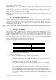
Install a 3U module into the crate slot by first placing the module’s card edges into the top and bottom guides. Place
the injector/ejector handle in the open position and slide the module to the rear of the crate. When you begin to feel
resistance, raise the handle to plug the module into the backplane connectors of the crate. Secure it by clipping the
handle into place. Tighten both front panel mounting screws to lock the module into place and insure proper
grounding of the frame.
2.4.3. Installing Filler Plug-in
CAUTION : The CC121 crate should not be used without closing all unused or empty slots.
To guarantee EMC performance and adequate cooling, install an optional XC200 Filler Plug-in or other filler panels
conform to IEEE1101.10 into all unused slots. Tighten both captive mounting screws to lock the panel into place and
insure proper grounding of the frame.
NOTE : Refer to the appendix 4.2
U1092A-C02 (U1056A-A11) XC200 6U Filler Plug-in, Specifications and
Assembly Instructions.
User Manual: Agilent Acqiris 21-slot cPCI Crate Page 10 of 19