USER MANUAL AGILENT ACQIRIS 21-SLOT CPCI CRATE
Manual Part Number U1092-90019 Edition C-RevE, June 2008 The information in this document is subject to change without notice and may not be construed in any way as a commitment by Agilent Technologies, Inc. While Agilent makes every effort to ensure the accuracy and contents of the document it assumes no responsibility for any errors that may appear. All software described in the document is furnished under license. The software may only be used and copied in accordance with the terms of license.
CONTENTS 1. OUT OF THE BOX ............................................................................................................. 4 1.1. Message to the User ...................................................................................................... 4 1.2. Before Using Your Crate............................................................................................... 4 1.3. Organization of This Manual....................................................................................
1. OUT OF THE BOX 1.1. Message to the User Congratulations on having purchased an Agilent Technologies Acqiris product. U1091AC21, CC121 21-slot 6U crates use the highest quality components and high output power supplies in order to maximize system performance and reliability. These universally applicable CompactPCI crates are carefully designed to yield high performance test systems for bench, lab and manufacturing test applications. 1.2.
product, the mains connector to the premise wiring must be disconnected. Dangerous voltages may be present under certain conditions, use extreme caution. Explosive Atmosphere : Do not operate the crate in conditions where flammable gases are present. Under such conditions this crate is unsafe and may ignite the gases or gas fumes. Part Replacement : Only service this crate with parts that are exact replacements, both electrically and mechanically.
• o product data sheets, o full installation procedures for use with Microsoft Windows, National Instruments LabVIEW RT, Wind River VxWorks, IVI-COM/C, and Linux software. Optional equipment. See the enclosed packing list. 1.8. Optional Equipment 1.8.1. CompactPCI 6U to 3U Slot Adapter The optional U1056A-A10 XC100 Slot Adapter is specially designed for use with Acqiris CompactPCI crates. This CompactPCI slot adapter allows the use of 3U modules in any vacant 6U slots.
1.11. Transport & Shipping To package the instrument for shipping: Step Notes 1. Place the instrument in its original packaging materials. • If the original packaging materials are not available, use a professional packaging service. Contact your Agilent Service Center for more information. 2. Surround the instrument with at least 3 to 4 inches (8 to 10 cm) of its original packing material or bubble-pack to prevent the instrument from moving in its shipping container. 3.
2. INSTALLATION 2.1. Configuration WARNING : Before connecting the crate to a power source, read this chapter and the paragraph 1.5.
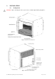
2.2. Site Considerations The CC121 is designed to be used either in a 19-inch instrument rack or in a bench-top configuration. It is delivered in the bench-top configuration with four feet screwed into the holes provided on the bottom of the crate. NOTE : With the feet in the bench-top configuration, the crate height is slightly more than the standard 9U .
you begin to feel resistance, push simultaneously both injector/ejector handles towards the center to plug the module into the backplane connectors of the crate. Secure it by clipping the handles into place. Tighten both front panel mounting screws to lock the module into place and insure proper grounding of the frame. 2.4.2. Installing 3U modules CAUTION : The XC100 6U to 3U Slot Adapter must be installed prior to inserting any 3U module into the CC121 crate.
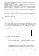
3. SPECIFICATIONS 3.1. Main Features The main features of the CC121 CompactPCI crate include : • 19 inch rack-mount crate, 9U high, 21 vertical slots with System Slot at the left and 20 Peripheral Slots. • CompactPCI (PICMG 2.0 R3.0) 6U and 3U module compatibility. The Backplane has three segments of seven slots linked with two CompactPCI bridge modules. These bridges are plugged on the rear of the backplane and all the slots are available for the application with complete access from the front side.
3.2.2. DC Outputs Specifications Maximum Usable Power 1900W @ 230VAC, 1260W @ 115VAC Output Voltages +3.3V: +3.3 ±0.1V +5V: +5.1 ±0.1V +12V: +12.15 ±0.15V -12V: -12.15 ±0.15V Maximum Output Currents +3.3V: 120A (400W) +5V: 120A (600W) +12V: 50A (600W) -12V: 25A (300W) RMS Ripple 0.1% or 10mV whichever is greater. 20MHz bandwidth Peak to Peak Noise 1% or 50mV whichever is greater. 20MHz bandwidth Dynamic Response <2% or 100mV @ 25% load step Recovery Time To within 1% in <0.
Slot Numbering Convention 3.4. Physical Logical (decimal) 1, 8, 15 4 2, 9, 16 15 3, 10, 17 14 4, 11, 18 13 5, 12 9 6, 13, 20 11 7, 14, 21 10 19 12 Backplane 3.4.1. Backplane Specifications Conformity CompactPCI: PICMG 2.0 R3.0 UL recognized Configuration 21 Slots, 1 System Slot to left, 20 Peripheral Slots. Three segments of seven slots linked with two transparent bridges plugged on the rear of the backplane.
3.4.2. Power Supply Status The Derating (DEG#) and Supply Fail (FAL#) are implemented only for the System Slot. Levels TTL levels, require pull-up resistor to +5V (2kOhm) on the System Controller Board. DEG# Mains AC accurate signal Indicate that the power supply is beginning to derate its power outputs. 1 = Mains AC is accurate. 0 to 1: 2msec minimum after the DC outputs are accurate. 1 to 0: 20msec minimum before FAL# and DC outputs are shutdown.
3.4.3. Connector Pinouts Connector P2 (J2) P1 (J1) Pin 22 21 20 19 18 17 16 15 14 13 12 11 10 9 8 7 6 5 4 3 2 1 25 24 23 22 21 20 19 18 17 16 15 12-14 11 10 9 8 7 6 5 4 3 2 1 Z GND GND GND GND GND GND GND GND GND GND GND GND GND GND GND GND GND GND GND GND GND GND GND GND GND GND GND GND GND GND GND GND GND A GA4 CLK6 CLK5 GND BRSVP2A18 BRSVP2A17 BRSVP2A16 BRSVP2A15 AD[35] AD[38] AD[42] AD[45] AD[49] AD[52] AD[56] AD[59] AD[63] C/BE[5]# V(I/0) CLK4 CLK2 CLK1 5V AD[1] 3.3V AD[7] 3.3V AD[12] 3.
3.5. Environmental 3.5.1. Environmental Specifications Operating Location Indoor use Operating Temperature 0° to 45° C Storage Temperature -40° to 85° C Operating Relative Humidity 5 to 95% non-condensing Operating Altitude 3000 m 3.5.2. Safety In accordance with Council Directive 73/23/EEC, Low Voltage Safety. Conformity EN61010-1 Installation Category II, Pollution Degree 2 Safety Class 1 3.5.3. EMC Emission In accordance with Council Directive 89/336/EEC, Electromagnetic Compatibility.
3.6. Mechanical 3.6.1. Mechanical Specifications Overall Dimensions Weight Width: Depth: Height: 483mm (19 in.) 440mm (17.32 in.) including the handles 399mm (15.71 in.) 9U 411mm (16.18 in.) including the feet 19.9kg (43.9 lb.) Enclosure: Material and Finish Steel sheet. Zinc plated. Outward painted Aluminum extrusion. Clear chromated Aluminum sheet. Clear chromated. Outward painted Handles: Aluminum. Black anodized Bus Bars: Copper. Nickel plated Card Guides: Molded plastic (UL 94V0 rated) 3.6.2.
4. APPENDICES 4.1.
4.2.