
Specifications


Legacy BIOS References
167
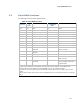
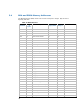
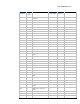
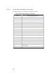
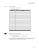
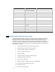
5.5 EBDA (Extended BIOS Data Area)
This area starts at the segment pointed to by the contents of 40:0E.
Table 17 Extended BIOS Data Area
Start
Location
Length
in
bytes
Description Modified by
Legacy BIOS
Comments
0x00 1 Length of EBDA in KB No
0x01 32 Reserved No
0x17 1 Number of POST errors No
0x18 5 POST error log No
0x22 4 Mouse Driver Ptr No INT74; Compatibility16 calls
this pointer
0x26 1 Mouse flag byte 1 Yes INT74
0x27 1 Mouse flag byte 2 Yes INT74
0x28 8 Mouse data Yes INT74
0x30 0x3D0 Reserved No
5.6 IA-32 and Itanium Processor Family Interrupts
EFI Environment
An EFI-only environment normally only has the timer interrupt hooked. The processor
traps, exceptions and faults are also trapped. There is only one supported hardware
interrupt for IA-32 (Timer interrupt). For the Itanium® processor family, the only
supported hardware interrupt is a processor counter ITC generated interrupt. There are
no software interrupts supported by either processor family.
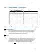
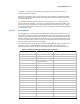
IA-32
Traditionally IRQ0 through IRQ7 are allocated to INT 0x08 through INT 0x0F, and IRQ8
through IRQ15 are allocated to INT 0x70 through INT 0x77. The traditional allocation of
INT 0x08 through INT 0x0F overlay with processor faults, exceptions and traps. It is safe
to move IRQ0 through IRQ7 to INT 0x68 through 0x6F, thus leaving INT 0x08 through
INT 0x0F free for the processor faults, exceptions and traps. The only interrupt
unmasked in the PIC registers 0x21 and 0xA1 should be the timer or IRQ0. APICs in
non-8259 mode are platform specific and outside the scope of this document.
SYNC1 IRQ0–7 are at traditional INTs and need to be moved.