User’s Guide for the C R AT E P R O A U D I O SPA-1400/1400C ¢¢¢¢¢¢¢¢¢¢ QQQQQQQQQQ ;;;;;;;;;; ÀÀÀÀÀÀÀÀÀÀ @@@@@@@@@@ ¢¢¢¢¢¢¢¢¢¢ QQQQQQQQQQ ;;;;;;;;;; ÀÀÀÀÀÀÀÀÀÀ @@@@@@@@@@ ¢¢¢¢¢¢¢¢¢¢ QQQQQQQQQQ ;;;;;;;;;; ÀÀÀÀÀÀÀÀÀÀ @@@@@@@@@@ ¢¢¢¢¢¢¢¢¢¢ QQQQQQQQQQ ;;;;;;;;;; ÀÀÀÀÀÀÀÀÀÀ @@@@@@@@@@ ¢¢¢¢¢¢¢¢¢¢ QQQQQQQQQQ ;;;;;;;;;; ÀÀÀÀÀÀÀÀÀÀ @@@@@@@@@@ ¢¢¢¢¢¢¢¢¢¢ QQQQQQQQQQ ;;;;;;;;;; ÀÀÀÀÀÀÀÀÀÀ @@@@@@@@@@ ¢¢¢¢¢¢¢¢¢¢ QQQQQQQQQQ ;;;;;;;;;; ÀÀÀÀÀÀÀÀÀÀ
SPA-1400/1400C Rack Mount Power Amplifier Contents: Introduction . . . . . . . . . . . . . . . . . . . . . . . . . . . . . . . . . . . . .3 Features . . . . . . . . . . . . . . . . . . . . . . . . . . . . . . . . . . . . . . . .3 Front Panel Information . . . . . . . . . . . . . . . . . . . . . . . . . . . . .4 Rear Panel Information . . . . . . . . . . . . . . . . . . . . . . . . . . . .5,6 Speaker Impedances And Power Ratings . . . . . . . . . . . . . . . .7 Installation and Operation Stereo Operation .
SPA-1400/1400C Rack Mount Power Amplifier Introduction: Congratulations. You have selected one of the finest pieces of sound reinforcement equipment available, the Crate Pro Audio SPA-1400/1400C Rack Mounted Amplifier. Our many years of experience in high-performance audio equipment, combined with our extensive research and development procedures, have enabled us to produce an amplifier which provides the highest quality and reliability possible.
SPA-1400/1400C Rack Mount Power Amplifier Front Panel Information: 1 @@@@@@@@@@ ÀÀÀÀÀÀÀÀÀÀ ;;;;;;;;;; QQQQQQQQQQ ¢¢¢¢¢¢¢¢¢¢ @@@@@@@@@@ ÀÀÀÀÀÀÀÀÀÀ ;;;;;;;;;; QQQQQQQQQQ ¢¢¢¢¢¢¢¢¢¢ @@@@@@@@@@ ÀÀÀÀÀÀÀÀÀÀ ;;;;;;;;;; QQQQQQQQQQ ¢¢¢¢¢¢¢¢¢¢ @@@@@@@@@@ ÀÀÀÀÀÀÀÀÀÀ ;;;;;;;;;; QQQQQQQQQQ ¢¢¢¢¢¢¢¢¢¢ @@@@@@@@@@ ÀÀÀÀÀÀÀÀÀÀ ;;;;;;;;;; QQQQQQQQQQ ¢¢¢¢¢¢¢¢¢¢ @@@@@@@@@@ ÀÀÀÀÀÀÀÀÀÀ ;;;;;;;;;; QQQQQQQQQQ ¢¢¢¢¢¢¢¢¢¢ @@@@@@@@@@ ÀÀÀÀÀÀÀÀÀÀ ;;;;;;;;;;
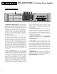
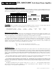
SPA-1400/1400C Rack Mount Power Amplifier Rear Panel Information – “Export”: (SPA-1400C ONLY) 18 19 20 21 22 23 24 21 20 19 18: BALANCED THRU/X-OVER OUT JACKS: These male XLR jacks are independently switchable and have two uses: (1) Balanced Thru: For driving additional amplifiers with the same input signal, set the X-OVER OUT/THRU switch (#19) to the THRU position (switch out). This places its corresponding Balanced Thru/X-Over Out jack in parallel to the same channel’s XLR and 1/4” input jacks.
SPA-1400/1400C Rack Mount Power Amplifier Speaker Impedances And Power Ratings: SYSTEM TWO TWO IN ONE PARALLEL SPKR When connecting speaker cabinets, you must observe proper load impedances. Whenever connecting multiple cabinets to an amplifier, the total load impedance must be calculated to insure proper performance from the amplifier. The table which follows shows the total load impedances of many common parallel speaker combinations: SINGLE SPEAKER 4Ω 8Ω 16Ω 4Ω 2Ω 2.7Ω 3.2Ω 2.7Ω 4Ω 5.3Ω 8Ω 3.2Ω 5.
Installation and Operation: Stereo Operation: The SPA-1400/1400Ccan be used in the Stereo Mode as two separate power amplifiers, each capable of driving loads down to 2 ohms. Each channel operates independently and has its own input connectors, sensitivity level controls, signal indicator LEDS, automatic limiter, fault protection circuitry, power amp, and speaker outputs. In the Stereo Mode, the MONO/STEREO SWITCHES (#16 & #17) must both be in the OUT position.
SPA-1400/1400C Rack Mount Power Amplifier Installation and Operation: Main/Monitor Combinations: Another application of the Stereo Mode (see page 8) is using one channel of the amplifier for the house speakers and the other for the monitors. The MONO/STEREO SWITCHES (#16 & #17) must both be in the OUT position. Either the binding posts or the Speakon® jacks may be used to connect the amplifier to the speakers. See the wiring diagram below for the Speakon® jacks.
SPA-1400/1400C Rack Mount Power Amplifier Installation and Operation: Parallel Mono Operation: The two internal power amplifiers (channel 1 and 2) can easily be driven by a single input signal. Connect the input signal to channel 1 and press in the PARALLEL MONO SWITCH (#16). (The BRIDGE MONO SWITCH, #17, must be in the OUT position!) The signal will be fed to both channels, each with its separate level control (#15).
SPA-1400/1400C Rack Mount Power Amplifier Installation and Operation: Bridged Mono Operation: The two internal power amplifiers can be bridged together to form a single, higher-powered amp. In the Bridged Mono Mode, the amplifier uses channel 1's INPUT jacks and LEVEL CONTROL; channel 2's are disconnected. Channel 2's power amp receives its signal from a tap after channel 1's LEVEL control, but prior to channel 2's Limiter, so each channel is independently protected.
SPA-1400/1400C Rack Mount Power Amplifier Installation and Operation: Patching Two Bridged Mono Mode Systems: Two Bridged Mono amplifiers can be patched together by connecting a signal cable between their input jacks (the dashed line in the illustration below). (On the SPA-1400C, another option is connecting a balanced XLR cable from the first amp’s BALANCED THRU jack [#18] to the XLR input of the next amp – the dotted line below.) The BRIDGE MONO SWITCH (#17) must be pressed in.
SPA-1400/1400C Rack Mount Power Amplifier Installation and Operation: Connecting Multiple Amplifiers (SPA-1400C only): A single signal may be passed along to multiple amplifiers by using the BALANCED THRU/X-OVER OUT jacks. Set the switches to the “Thru” (OUT) position and connect from the first amplifier’s Balanced Thru jack to the next amp’s input jack. Make all other connections (from mixer, to speakers, etc.) per normal, as each amplifier/speaker combination requires.
SPA-1400/1400C Rack Mount Power Amplifier Installation and Operation: Biamping: SPA-1400 – One Amp, Single Cabinet: One SPA-1400 can be used to separately power the lows and highs of a cabinet with biamp inputs. The MONO/STEREO SWITCHES (#16 & #17) must both be in the OUT position. (We show use of channel 1 for the low frequencies and channel 2 for the highs, but you may choose to use 1 for the highs and 2 for the lows.
SPA-1400/1400C Rack Mount Power Amplifier Installation and Operation: Biamping: SPA-1400 – One Amp, Separate Cabinets: One SPA-1400 can be used to power separate low and high frequency cabinets. The MONO/STEREO SWITCHES (#16 & #17) must both be in the OUT position. (We show use of channel 1 for the low frequencies and channel 2 for the highs, but you may choose to use 1 for the highs and 2 for the lows.) A separate external electronic crossover must be added between the mixer and the power amp.
SPA-1400/1400C Rack Mount Power Amplifier Installation and Operation: Biamping: SPA-1400C – One Stereo Amplifier: A single SPA-1400C can be used to power separate low and high frequency cabinets (shown below), or to separately power the lows and highs of a cabinet with biamp inputs (for speaker connection information see page 14). The MONO/STEREO SWITCHES (#16 & #17) must both be in the OUT position.
SPA-1400/1400C Rack Mount Power Amplifier Installation and Operation: Biamping: SPA-1400C – Multiple Amplifiers: A single SPA-1400C can be used to power separate low and high frequency cabinets (shown below), and to connect additional biamped speakers, using multiple amplifiers. The MONO/STEREO SWITCHES (#16 & #17) must both be in the OUT position.
SPA-1400/1400C Rack Mount Power Amplifier Installation and Operation: Biamping: SPA-1400C – Two Mono Bridged Amplifiers: A pair of SPA-1400C can be used to power separate low and high frequency cabinets. The BRIDGE MONO SWITCH (#17) of each amplifier must both be in the IN position. Use one amplifier for the low frequencies and the other for the highs.
SPA-1400/1400C Rack Mount Power Amplifier Installation and Operation: Triamping: SPA-1400: A pair of SPA-1400s can be used to power separate low, mid and high frequency cabinets, or a separate subwoofer and biamped full range cabinet. In the example shown below, with a mono bridged subwoofer configuration, the BRIDGE MONO SWITCH (#17) of the low frequency amplifier must be pressed in; the MONO/STEREO SWITCHES (#16 & #17) of the mid/high frequency amplifier must both be in the out position.
SPA-1400/1400C Rack Mount Power Amplifier Installation and Operation: Triamping: SPA-1400C: A pair of SPA-1400Cs can be used to power separate low, mid and high frequency cabinets, or a separate subwoofer and biamped full range cabinet. In the example shown, a bridged mono subwoofer, the BRIDGE MONO SWITCH (#17) of the low frequency amplifier must be in the IN position; the MONO/STEREO SWITCHES (#16 & #17) of the mid/high frequency amplifier must both be in the OUT position.
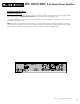
SPA-1400/1400C Rack Mount Power Amplifier System Block Diagram, SPA-1400: RING RED (+) CH 2 OUTPUT BINDING POSTS TIP 2 CH 2 INPUTS + PARALLEL MONO ST CH 2 LEVEL 3 BRIDGE MONO ST CH 2 AMP BLK (–) 1 CH 2 OUTPUT 1+ SPEAKON ® JACK MONO MONO LIMITER 1– 2– 2+ PROTECT LIMIT SIGNAL 1– SIGNAL MONO/ BIAMP 1+ SPEAKON ® JACK 2– 2+ LIMIT CH 1 OUTPUT 1+ SPEAKON ® JACK PROTECT CONTROL RING 1– TIP 2 CH 1 INPUTS CH 1 AMP CH 1 LEVEL 2– 2+ RED (+) + 3 CH 1 OUTPUT BINDING POSTS 1 BLK (–) LIMIT
SPA-1400/1400C Rack Mount Power Amplifier Mode Block Diagrams: The following diagrams are excerpts from the system block diagrams and are intended to provide a simplified view of the three operating modes of the amplifier. For more complete information please refer to the text on page 5 (items #16 & 17), and the text and/or illustrations on pages 8 – 21.
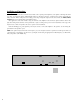
SPA-1400/1400C Rack Mount Power Amplifier Installation Notes / Mounting Dimensions: The SPA-1400/1400C is specifically designed to be rack mounted, either as a permanent fixture or in a “mobile” rack case. As with any large, heavy object, a proper installation could mean the difference between success and disaster. The front of the unit is designed to attach to standard rack rails. The four outermost holes correspond to the screw holes on standard rack rails (2 rack spaces in height).
SPA-1400/1400C Rack Mount Power Amplifier Technical Specifications POWER OUTPUT Stereo Mode: 260 watts / channel @ 8 ohms 20Hz–20kHz 425 watts / channel @ 4 ohms 20Hz–20kHz 660 watts / channel @ 2 ohms 1kHz Bridged Mono Mode: 520 watts / channel @ 16 ohms 20Hz–20kHz 850 watts / channel @ 8 ohms 20Hz–20kHz 1320 watts / channel @ 4 ohms 1kHz FREQUENCY RESPONSE +0/-.4dB, 20Hz – 20kHz TOTAL HARMONIC DISTORTION < .25%, 20Hz–20kHz @ 400 watts / channel 4 ohms (typically .