
User Manual


SERVOS & PUSH RODS
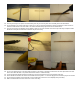
112. The servos should sit no more than 2” (0-5 cm) in front of the upright tail piece with the arms facing outwards, and the leads
pointing towards the nose of the plane.
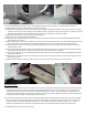
113. The servos can either be upright or laid on their side. Both methods work well.
114. Lay the servos in place and mark the fuselage in front and behind them for a pattern to cut on.
115. Use a straight edge and razor blade to cut across the fuselage at the front and back marks for the servo. Cut only as deep as you
need to for the servos to lay flush with the top of the fuselage.
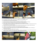
116. Cut a slot for the servo and other radio wiring. The receiver and ESC will also be on this line.
117. Use hot glue to set the servos in place
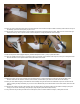
118. EZ connectors can be on the servo arm or on the horn at the back of the plane.
119. Connect your radio and center the servo arms with transmitter on. You may have to remove and replace the arm for this.
120. Slide the Z-bend end of one of the push rods into the servo arm, so that the push rod extends back from the inside of the servo
arm. If the push rod or EZ connector does not fit, you may have to use a drill to widen the holes in the servo arm and horn.
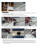
121. Lay the other end of the push rod on the elevator straight back from the servo. Place a mark on the front edge of the elevator,
where the push rod will go.