Technical Manual Including Spare Parts Information Part No.
Technical Manual Contents Page No. Introduction ...................................................................................................2 Important Information.................................................................................2 Section 1 - Machine Specifications............................................................3 Section 2 - Installation Procedure ............................................................7 Section 3 - Programming Mode ....................................
Technical Manual Introduction This machine has been designed to our own rigid safety and performance standards. It has been designed to comply with sanitation and health guidlines recommended by the Automatic Merchandising Health-Industry Council (AMHIC) and it conforms with all other NAMA safety recommendations. This machine has been manufactured in accordance with the safety standards of both Underwriter’s Laboratories and the Canadian Standards Association.
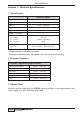
Technical Manual Section 1 - Machine Specifications 1.1 Specifications Espresso (B2C) Height 33.85 in. (860 mm)* Depth 23.23 in. (590 mm) Width 21.26 in. (540 mm) Weight 154 lbs. (70 kg) Cup Capacity 230 Number of Canisters Electrical Requirements (i) Voltage (ii) Current (iii) Frequency Water Services Pressure 6 115 V ac 12 Amp, single phase 60Hz 10 psi (69 KPa) - 80 psi (522 KPa) * Height includes visible bean container. All weights and dimensions are approximate and are for guidance only. 1.
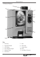
Technical Manual 1.4 External Features 11 1 10 2 3 4 9 5 8 6 7 Key: 1. Coin Entry 7. Foot 2. Coin Reject Button 8. Door Lock 3. LCD Display 9. Graphic Panel 4. Drink Selection Keypad 10. Door 5. Selection Decals 11. Fresh Beans Container 6.
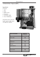
Technical Manual 1.5 Internal Features 1 3 2 14 4 13 5 12 11 6 10 9 8 7 Key: 1. Soluble Ingredient Canister 8. Waste Tray Grill 2. Freshbrew Coffee Canister 9. Moving Dispense Head 3. Fresh Beans Container 10. Door Switch 4. Main Wire Harness 11. Mixing System 5. CoEx® Brewer 12. Cup Drop Unit 6. Brewer Waste Bucket 13. Canister Outlet 7. Waste Tray 14.
Technical Manual 1.6 Drinks Choice - Espresso (B2C) Ingredients: 6 Canisters 1. Milk 2. Sugar 3. French Vanilla 4. Chocolate 5. Freshbrew Coffee 6. Fresh Coffee Beans All speciality drinks made with freshly ground coffee beans and cappuccino topping.
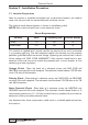
Technical Manual Section 2 - Installation Procedure 2.1 Location Preparation After the machine is unpacked and placed near its permanent location, you need to make sure that you have the correct electrical and water service. The machine needs electrical power as shown in the following table. NOTE: Each machine should have its own electrical circuit.
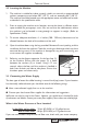
Technical Manual 2.2 Locating the Machine 1. The machine is suitable for indoor use only, sited in an area with a recommended ambient temperature not below 50°F (10º C) and not exceeding 86°F (30º C). The machine should be located near the appropriate water and electrical services as detailed in the specification table. 2.
Technical Manual 2.4 What to do With the Water Supply Line: ● Locate the supply line at the rear of the machine ● Equip the line with a shut-off valve 1. Flush the water supply line before connecting it to the machine. A minimum of 5 gallons is usually required before connecting the machine to the supply line. DO NOT flush the machines water system. If you do, you might introduce water line contaminants into the machine. 2.
Technical Manual 2.6 Set-Up Procedure 1. Ensure that the electrical and water services to the machine are connected correctly and turned on. Ensure that the waste tray is fitted correctly to the machine. Open the front door of the machine and swing the cup turret assembly out of the machine. 2. Soluble Ingredient Canisters: Rotate soluble ingredient canister outlets to upright position and remove the canisters - DO NOT place ingredient canisters on the floor. Remove the canister lids.
Technical Manual mechanism will index the first available full cup stack to the dispense position and drop the cup stack into the cup drop mechanism. Fill the remaining empty cup stack with cups and replace the turret cap. 5. While the machine is powering up, the LCD will display the message as shown opposite. As the machine initializes a small amount of water is pumped through the system and is discharged into the waste tray. When the machine enters standby mode remove the tray and empty the contents.
Technical Manual 9. Pull the bean canister shut-off (a) to its fully extended position as shown in the photograph. a Ensure that the brewer waste container is fitted correctly beneath the CoEx® brewer unit. 10. If fitted, check that the coin mechanism and cash box operate correctly. Fill the coin tubes with correct coinage. Ensure coin return mechanism functions correctly. 11. Operate the machine through its complete range of selections to ensure that each vend is correctly dispensed.
Technical Manual Section 3 - Programming Mode 3.1 Drink Selection Keypad Programming mode utilises the drink selection keypad, as defined in the illustration below, and allows the engineer to view and alter stored data within the machines memory.
Technical Manual $0.05. This is a useful way to quickly check stored settings and also confirm that a value has been altered correctly. 5. To return to the Main Menu from any screen, simply press the X (Exit) key until you reach the Main Menu. 3.3 Accessing the Programming Mode 1. Open the door of the machine and insert the door switch key to restore power to the machine. The machine is now on. 2. Press the Program Entry key (1) on the service keypad, located inside the door (see page 56 for details).
Technical Manual 6. Using the ▲ (up) or ▼ (down) keys, the ↵ (Edit) key and the X (Exit) key it is possible to easily navigate through all of the menus contained within the Engineers Program. 7. To update parameters, key in the actual digits of the number required using the selection keys 0-9. Once the correct parameter has been entered, press the ↵ (Edit) key to overwrite the previous value and save the new parameter in the machines memory.
Technical Manual Section 4 - Engineers Program Main Menu To access the Engineers Program, enter the programming mode as described in section 3. Once in the Engineers Program the LCD on the front of the machine will display the top level programming menu screen - Main Menu. Note: Coins In/Out will only be displayed on machines fitted with an MDB coin mech.
Technical Manual Discount-$ Discount-# Test Vend-$ Test Vend-# Surcharge-$ Surcharge-# Free Vend-$ Free Vend-# Displays Displays Displays Displays Displays Displays Displays Displays the the the the the the the the total total total total total total total total monetary value of all discounts in $ number of discounted vends monetary value of all test vends in $ number of test vends monetary value of all surcharges in $ number of surcharge vends monetary value of all free vends in $ number of free vends
Technical Manual the machine to the previous screen. The engineer can then view data for more selections using the procedure described above and also access further menus via the Non Resettable Sales Data menu relating to Cash, Cashless and Token audit data. 8. To return the machine to standby mode, press the X (Exit) key repeatedly until the LCD displays the standby screen. 2. Resettable Sales Data: This menu contains similar data to that available from the Non Resettable Sales Data menu.
Technical Manual Once the engineer has viewed and recorded required information from these submenu’s, the data can be deleted via the Clear Data sub menu. 5. From the Resettable Sales Data screen, highlight the Clear Data sub menu using the ▼ (down) key and press the ↵ (Edit) key. The LCD on the front of the machine will display the screen as shown opposite, warning the engineer that all data will be deleted.
Technical Manual 5. SureVend: This menu becomes available when SureVend is enabled via the Product Configuration menu (see page 30). 1. 2. From the Data Recall menu scroll down and highlight SureVend then press the ↵ (Edit) key. The LCD will display the screen as shown opposite. From this menu screen the engineer can view and record the number of cup drop failures that SureVend has logged and also the number of SureVend assisted vends.
Technical Manual 4.3 Test Menu This menu allows the engineer to test individual components and switch inputs to ensure correct operation. On entry into the Test menu the LCD will display the screen as shown. Test Cup Mechanism Hot Vend Test Dispense Head Switches & Sensors Test Vend Without Cups Press EDIT to Select Test Vend Grinder Test Display Keypad Entry 1.
Technical Manual 2. Whipper: This sub menu allows the engineer to test for correct operation of each individual whipper assembly fitted to the machine. Press the ↵ (Edit) key to display the test screen which indicates the number of whippers fitted to the machine. 1. To test a whipper, press the corresponding button on the drink selection keypad. The selection will be highlighted as shown and the whipper will run for 3 seconds. Repeat this operation to test additional whipper units.
Technical Manual that the waste tray is empty. Press the ▲ (up) or ▼ (down) keys to highlight the other switch/sensor inputs and view their status. Mug Sensor - Current: This menu gives the engineer an indication as to the efficiency of the SureVend™ sensor. The range for correct operation is a numerical value between 51 - 255. 1. 2. Highlight Mug Sensor - Current from the Switches & Sensors menu and press the ↵ (Edit) key. The LCD will display the screen as shown opposite.
Technical Manual 6. Test Vend: This menu allows the engineer to make a test vend in order to verify that the dispensed vend is acceptable. 1. Highlight Test Vend in the main Test menu and press the ↵ (Edit) key. The LCD will display the screen as shown opposite. Time 03:22 2. Make a selection using the drink selection keypad and press the START button. The machine will drop a cup before dispensing the selection.
Technical Manual 2. 3. To test the Main Keypad, press the ↵ (Edit) key to access the test screen. Press any key on the drink selection keypad and verify that it is displayed correctly. Example; pressing the START key on the drink selection keypad will display the screen as shown opposite. Main Keypad Start Press Key And Verify Press the X (Exit) key to return to the Keypad Entry menu screen. Use the ▼ (down) key to highlight Service Keypad and press the ↵ (Edit) key to access its test screen.
Technical Manual 4. Press the ↵ (Edit) key to return to the Individual Prices screen and verify that the new price displays in the status line along the bottom of the display. Use the ▲ (up) or ▼ (down) keys to highlight further selections. 2. Entire Machine: This sub menu allows the engineer to set a single price for all selections available from the machine. 1. 2. When highlighted from within the Price menu, the LCD will display the screen, with the current value (e.g. $1.50), as shown.
Technical Manual 2. To enter a discount value, e.g. $0.10, press the sequence 0-0-0-1-0 using the appropriate number keys on the drink selection keypad. 3. The LCD will change and display the screen as shown. Press the ↵ (Edit) key to return to the Price menu screen and verify that the new price displays in the status line along the bottom of the display. Mug Discount 000.10 0-9 to Edit Value Edit when Finished 4.
Technical Manual 2. The following examples describe how to adjust the Gourmet Coffee recipe made from fresh beans. 3. With Gourmet Coffee highlighted in the Selection Timers menu, press the ↵ (Edit) key to access the Gourmet Coffee Timers menu. This menu, shown opposite, contains the three ingredients which may be required in a gourmet coffee from ground beans selection. 4.
Technical Manual under or over-fill. 9. Each drink selection available from the machine will be made up with different selection timers, for example the Café Mocha recipe will contain timers for Chocolate, Fresh Coffee Beans and Milk and will also contain whipper timers which control how the selection is mixed and presented in the cup. 10. Product, Whipper and Post Dispense Delays Product Delay - This determines the time interval between the water valve start and the start of the product ingredient motor.
Technical Manual to any drink selections that have been disabled, indicating to the customer that the drink choice is un-available. 4. SureVend: Entry into this menu allows the engineer to turn the SureVend™ product delivery sensor on or off. SureVend™ Overview: 1. SureVend™ ensures that a cup is always available in the cup station before any money is collected or product delivered.
Technical Manual 3. Press the ↵ (Edit) key to confirm the selection and return to the SureVend screen. Verify that the status line at the bottom of the screen displays Off when SureVend is highlighted. 4. Pressing the X (Exit) key will move back to the Product Configuration screen and save the new parameter to the machines memory. 5. Cup Size Selection: This sub menu allows the engineer to quickly and easily change the cup size dispensed by the machine, either 8oz or 9oz when required. 1.
Technical Manual espresso drink types available from the machine. To adjust the water compensation values, proceed as follows: 1. From the Product Configuration menu highlight Water Compensation and press the ↵ (Edit) key to access the menu screen as Water Compensation shown. Using the ▲ (up) or ▼ (down) keys, Soluble Compensation Compensation scroll through the menu until the required drink FB Esp Compensation type is highlighted e.g. Esp Compensation for espresso and espresso based selections.
Technical Manual 20 ml for sugar. Return the machine to standby mode and vend an espresso (no sugar) selection. Carefully measure the amount of water dispensed. If the dispensed amount is less or more than 60 ml, return to the Water Compensation menu as described above and enter the Esp Compensation sub menu - default value 160. Enter a value higher (e.g. 165) or lower (e.g. 155), return to standby, vend a second espresso selection and measure the amount of water dispensed.
Technical Manual 4. The LCD will now display the menu screen as shown opposite. Weigh the cup and its contents and enter the weight into the machine. If the weight of ground coffee was 6.5 grams, enter 00-6-5 using the drink selection keypad. Empty the contents of the cup and press the START key to continue calibrating the grinder. 5. Repeat steps 3 and 4 twice more. Upon completion the LCD will change and display the new calibrated value as a value of grams per second as the example shown.
Technical Manual Important: Once the brewer waste container has been emptied, cleaned and re-fitted to the machine, the waste counter must be reset by pressing button 12 on the service keypad mounted inside the door. The machine will bleep twice to confirm that the counter has been reset. 4. To turn waste management Off, highlight Brewer Waste Management from the Brewer Waste Management screen. Press the ↵ (Edit) key to display the screen as shown.
Technical Manual Coins In/Out Coin Count 0.05 34 0.10 18 0.25 9 8 1.00 1. From the Main Menu screen use the ▼ (down) key to scroll through the menu until Coins In/Out is highlighted. Press the ↵ (Edit) key to access the menu screen which will look similar to the example shown. 2. From this screen the engineer can view the coin sets in the coin mechanism, the number of coins in each coin stack and the total value of the coins.
Technical Manual The 1= 2= 3= 4= 5= keys are configured as follows: ,.?';:"1 6= mno 6 abc 2 7= pqrs 7 def 3 8= tuv 8 ghi 4 9= wxyz 9 jkl 5 0= -\$@%#&0 Note: To change from lower to upper case, press the START key. 3. When complete, press the X (Exit) key to return to the Machine Information menu screen. Press the ▼ (down) then ↵ (Edit) keys to highlight then enter the Machine Location screen. Enter a unique machine location using the 0-9 drink selection keys as described above.
Technical Manual As the engineer presses the final zero, the AM value will appear within a dotted box and the text at the bottom of the LCD will now read ‘Press Arrows To Select’. Press the ▲ (up) or ▼ (down) key until PM appears in the box. Time hh / mm / mode: 12 / 24 10 : 30 PM Press Arrows To Select Pressing the ↵ (Edit) key will move back to the Clock menu screen and save the new time to the machines memory.
Technical Manual The Monetary menu can display up to 11 sub menus, depending on machine configuration, as listed below: • • • • • • • • • • • Coin Mechanism Bill Validator Card Reader Bill Stack Option Multiple Vend Mode (Only if MDB mech. selected) Change Without Purchase (Only if MDB mech. selected) Low Change Message (Only if MDB mech. selected) Accept On Low Change (Only if MDB mech. selected) Credit for Failed Vend (Only if MDB mech.
Technical Manual 1. 2. From the Monetary menu press the ▼ (down) key to scroll down and highlight Card Reader and press the ↵ (Edit) key. Using the ▲ (up) or ▼ (down) keys, select the desired card reader option (indicated by the filled radio button). Card Reader No Card MDB Card Digi Card Press the ↵ (Edit) key to save the selection and return to the Monetary menu. Verify that the chosen option is displayed in the status line at the bottom of the display. 4.
Technical Manual change to a customer. If the customer deposits credit into the machine which is less than or equal to the value set in the Change Without Purchase menu, change will be returned without a purchase. However, if the credit is larger, the customer must make a purchase before change will be given. Examples: Value set to 01.00: Non-escrowed coins less than or equal to $1.00 will be changed without purchase. All escrowed coins are returned. Value set to 00.00: Forced Vend.
Technical Manual Verify that the entered value is displayed in the status line at the bottom of the display when Low Change Message is highlighted. Note: The machine will still accept money with this value set, but may short change the customer if there is insufficient coinage in the coin mechanism. Set the Low Change Message and the Accept on Low Change values to the same figure to eliminate any chance that the customer will be short changed. 8.
Technical Manual 1. 2. From the Monetary menu press the ▼ (down) key and highlight Credit For Failed Vend and press the ↵ (Edit) key. Using the ▲ (up) or ▼ (down) keys, select the desired option (indicated by the filled radio button). Credit For Failed Vend Hold Credit Return Change Press the ↵ (Edit) key to save the selection and return to the Monetary menu. Verify that the chosen option is displayed in the status line at the bottom of the display when Credit For Failed Vend is highlighted. 10.
Technical Manual data carrier or other device. Data Transfer Standard (EVA-DTS) - Overview: The standard makes it possible to transfer information from vending machines/payment systems to PC-based accounting/management systems and/or the opposite way.
Technical Manual DEX/DDCMP report. When set to numeric it will read 3. 4. Data Reset Mode: This field can be set to either AUTO or SAVE from within the sub-menu. When set to AUTO, all resettable data will be reset after a successful read. 5. Event Reset Mode: This field can be set to either AUTO or SAVE from within the sub-menu. When set to AUTO, all event data will be reset after a successful read. 6.
Technical Manual Close the door and restore power to the machine. 2. 3. Enter the engineers program as previously described. Access the Systems Settings menu and using the ▼ (down) key highlight Serial Flash. Press the ↵ (Edit) key to enter the sub program. If an empty card is being used the LCD will display the screen as shown.
Technical Manual 1. 2. 3. 4. Scroll down and highlight Backup/Restore from the System Settings menu. Press the ↵ (Edit) key to access the menu. If this is the first time that a backup has been selected the LCD will display the screen as shown. Press the ↵ (Edit) key to access the menu. The LCD will display the screen as shown. To backup the memory press the ↵ (Edit) key.
Technical Manual display when Screen Contrast is highlighted. 9. Software Version: The Software version menu displays the version number of the software installed and is for information only. The menu also displays the current time and date. 10. I/O Board Software: This menu displays the version number of the I/O board software installed and is for information only. 11. Temperature Units: This menu is not applicable to Genesis B2C machines. 12.
Technical Manual 2. To change the engineer entry code, press the ▼ (down) key to highlight Engineer Program then press the ↵ (Edit) key. The LCD will display the Edit Pin screen as shown. Enter a new pin number using the drink selection keypad and press the ↵ (Edit) key. Engineer Program 0158 0-9 to Edit Value EDIT when Finished Note: This security number is not displayed. Be sure to record the new pin code and keep it in a safe place. 3.
Technical Manual 4. 5. Press the ▼ (down) key to highlight Event Type and press the ↵ (Edit) key to access the menu. Using the ▼ (down) key, set the Event Type to Free Vend (indicated by the filled radio button). Press the ↵ (Edit) key to return to the Event 1 screen. Verify that the status line confirms the Event Type is set to Free Vend. Press the ▼ (down) key to highlight Start Time and press the ↵ (Edit) key. From this menu the engineer sets the time at which the free vend period will start.
Technical Manual 10. Press the ▼ (down) key to highlight Selections Selections and press the ↵ (Edit) key. The engineer can now X Espresso set the drink selections that will be available X Double Espresso X Hot Chocolate during the free vend period. Upon entry to the Cappuccino Caffe Mocha sub menu, the Espresso selection will be Start = Set or Clear All highlighted with an empty box. Pressing the ↵ (Edit) key will select the day, indicated by an X appearing in its adjacent box.
Technical Manual 2. Sanitation Events Menu: This sub menu allows the engineer to select periods when the machine will automatically rinse through the water system via the 6 timed and 6 post vend rinse periods available. The default setting for all rinse periods is Off. 1. From the Main Menu press the ▼ (down) key until Timed Events is highlighted then press the ↵ (Edit) key. Sanitation Events Menu 2.
Technical Manual 6. Press the ▼ (down) key to highlight Days Of Week and press the ↵ (Edit) key. From this menu the engineer can set the days on Days of Week which the sanitation event will take place. To X Monday Tuesday select everyday (Monday - Sunday), press the X X Wednesday START key on the drink selection keypad. The X Thursday program automatically places an X in every box X Friday Start = Set or Clear All indicating that each day is selected.
Technical Manual 4. 5. Press the ▼ (down) key to highlight Event Type. By default the event is set to Timed as indicated by the text displayed in the status line at the bottom of the screen. Therefore it is not necessary for the engineer to enter this sub menu. 7 State Event Type Delay Post Vend Press the ▼ (down) key to highlight Delay. The status line indicates the factory default delay which is set to 0.1hrs (6 minutes).
Technical Manual 4. 5. Press the ↵ (Edit) key to access the State sub menu. Using the ▼ (down) key, set the state to On (indicated by the filled radio button). Press the ↵ (Edit) key and verify that the status line confirms the State is set to On. Press the ▼ (down) key to highlight Start Time and press the ↵ (Edit) key. Using the drink selection keypad, set the time at which the the Backup event will start. If necessary use the ▲ (up) or ▼ (down) key until AM appears in the dotted box.
Technical Manual Section 5 - Service Keypad Functions Genesis machines are fitted with a service keypad (a) mounted on the rear of the door (photo). This keypad contains the Engineers Program entry key and also allows the engineer/operator to carry out specific functions during routine cleaning and maintenance. Note: During certain operations e.g. View Counters it is necessary for the engineer to utilize the selection keypad and LCD mounted on the front of the door to access data.
Technical Manual Resettable Sales Data and SureVend™ Data menus contain an extra sub-menu which allows the engineer to delete the current data from the machines memory. Full details relating to this menu and its contents can be found on pages 16 - 18. 5.4 Switch 6 - Test Vend The Test Vend switch (6) allows the engineer to vend a drink from the machine to ensure correct operation after cleaning or maintenance. 1. When the switch is pressed and released the LCD will display the screen as shown opposite.
Technical Manual oz. (370 ml) is dispensed from the system. Ensure a container is placed under the dispense head to collect the water. When complete the LCD will display the message ‘Machine Cooled’ and all switch inputs are disabled. Once the power to the machine is disconnected the engineer can then work safely on the water system. 5.9 Switch 11 - CoEx® Tablet Clean This switch when pressed initiates the CoEx® brewer tablet cleaning routine.
Technical Manual 5.11 Switch 14 - Clear SureVend Error This switch when pressed allows the engineer to simply and quickly clear SureVend errors caused by cup failures.
Technical Manual Section 6 - The Vend Cycle 6.1 Standby Mode In standby mode the machine is idle, awaiting input from the drink selection keypad. The LCD will display to the customer one of a number of messages indicating the credit mechanism of the machine, the coin set and the time. The messages displayed are determined by the type of coin system which has been programmed via the System Settings menu (Section 4, page 38). The credit mechanism is indicated by one of the following prompts: 1.
Technical Manual Note: The default strength setting for this drink selection is Normal as shown. 2. To obtain a Strong or Mild beverage it is necessary to press the current drink selection button. Pressing once will toggle to the Strong selection. Pressing the button again will toggle to the Mild selection. Gourmet Coffee Gourmet Coffee Pressing the current drink selection button again will revert to the Normal screen. 3.
Technical Manual 7. Once the required drink has been selected, press the Start button on the keypad. All lit buttons will be extinguished apart from the drink selection button which flashes indicating that the drink is being vended. Unless the customer has placed their own cup into the dispense area, a cup will automatically be ejected from the cup drop unit into the dispense area and the drink selection will be delivered into the cup.
Technical Manual 6.3 Replacing/Updating Drink Selection Decals Drink selection and pricing decals are mounted onto a paper backing sheet which is secured behind a transparent clip-in cover. To update drink pricing or replace drink description decals, proceed as follows: 1. Carefully unclip the transparent decal cover from the door using the snap fit clip at the top. Remove the decal sheet from its holder as shown opposite. 2.
Technical Manual Section 7 - Technical Information 7.1 Water Services The water supply provides water for the pressure system fitted to Genesis B2C machines. Water enters at the rear of the machine through a solenoid operated inlet valve operating at 24v DC, which opens or closes the water supply as required. The water system fitted to Genesis machines is described in detail in Section 8 of this manual (8.2 - System Overview). 7.2 Ingredient Dispense 1.
Technical Manual 2. The mixing units are front mounted and secured by a single fixing screw. For servicing, the complete unit can be quickly and easily removed from the front of the machine. Note: An illustration showing the parts breakdown for the Mixing System is included in Section 12 - page 115. 7.4 Moving Dispense Head 1. Genesis machines are fitted with a moving dispense head mechanism. This allows for a quicker and more direct cup drop and also helps to prevent cross contamination of drinks.
Technical Manual 4. The cup level is monitored by an electronic system. An infrared LED (cup sensor transmitter) is positioned in the cup assembly above the cup ring, with an infrared detector (cup sensor receiver) mounted directly opposite. 5. The light emitted by the LED is detected when NO CUPS are present. With a stack of cups present, the beam is broken. As the cups drop below the LED, transmitted light is detected.
Technical Manual 7.8 Power Supply Unit 1. The power supply unit (PSU) provides power to the machine. It is mounted on the PSU chassis on the left hand side of the machine and can be accessed by removing the lower front panel. 2. The PSU converts 115v AC to 24v DC to run the valves, whipper motors, ingredient motors, brewers, etc. fitted to the machine. The solid state relay, mounted on the PSU chassis, uses a 24v DC switching circuit to provide 115v AC for the heater element. 3.
Technical Manual 7.12 Coin Mechanism 1. The Coin Mechanism communicates with the vending machine controller through a serial communication interface. It will validate a coin and if accepted, send a signal to the vending machine controller indicating the total amount of money which has been tendered since the last vend. 2. Once sufficient credit has been accumulated a vend will be permitted. Where possible the coin mechanism will return the appropriate amount of change to the customer. 7.
Technical Manual Section 8 - Espresso (B2C) System Genesis B2C machines are capable of producing high quality espresso based drinks through the unique CoEx® brewer unit either independently (Espresso, Americano), or in conjunction with the soluble product (Cappuccino, Caffe Mocha etc). The machine can also vend high quality freshbrew coffee from pre-ground product. 8.1 Example Vend When an Espresso drink is selected the following sequence occurs:1. The customer selects an espresso drink.
Technical Manual copper, iron, cadmium), chlorine and any organic pollutants/discolouration. 1. Water Inlet Valve A 24V dc single solenoid water inlet valve. When a drink is selected the inlet valve is opened. At the same time the pumps are operated, pumping water through the system. 2. Reducing Valve An inline reducing valve that maintains water pressure within the system at 0.5 bar. 3.
Technical Manual 10. Grinder Mechanism (Not Shown On Water Flow Diagram) The grind mechanism consists of a 115V ac conical grinder with a manual adjustment. When an espresso based drink is selected the grinder will run for the required time, grinding beans and feeding the brewer at the same time. The grinder is fitted with a manual adjusting mechanism which allows the engineer to vary the size of the ground coffee in order to satisfy customers’ taste preferences. 11.
Technical Manual Section 9 - Dispense Tube Lengths H 4 3 1 2 Tube No 1 2 3 4 Diameter 0.236 0.236 0.236 0.315 in in in in (6 (6 (6 (8 mm) mm) mm) mm) I.D. I.D. I.D. I.D. x x x x 0.394 0.394 0.394 0.512 Length in in in in (10 (10 (10 (13 mm) mm) mm) mm) O.D. O.D. O.D. O.D. H = Hot Water Dispense Tube French Vanilla Hot Chocolate 72 6.693 in (170 mm) 6.299 in (160 mm) 6.693 in (170 mm) 14.
Technical Manual Section 10 - Electrical/Electronic Diagrams The diagrams shown on the following pages illustrate the layout of, and the connections between, the electrical and electronic components within Genesis B2C machines. 10.
Technical Manual 10.2 Control Board The Control Board is the main controller for all of the machines functions. The board is located inside the door behind the monetary cover. To gain access to the board: 1. Switch off the power to the machine and open the front door. Unscrew and remove the two knurled thumbscrews securing the monetary cover. 2. Open the monetary cover. Loosen the four screws securing the control board cover and remove.
SUREVEND SENSOR BLACK WHITE PLUG RED RED BLUE BLACK THERMISTOR PRESSURE TANK RED BLUE BLACK WHITE BLACK 1 2 3 4 5 6 7 8 9 J4 J9A 5V+ } SURE VEND SENSOR } THERMISTOR MAIN CONTROLLER BOARD LED 2 POWER J5 J6 CONSOLE IrDA J10 CONSOLE LED 1 COMMUNICATIONS IR OUT-TX IR IN-TX THERM COM THERM OUT J9B MAIN CONTROLLER BOARD LINK RIBBON CABLE Technical Manual 10.
Technical Manual 10.4 Control Board Connections - 2 The diagram below illustrates the connections between the control board and the input/output board, coin mechanism communications and the switch mode power supply.
Technical Manual 10.5 Input/Output Board The Input/Output Board is mounted onto the power supply chassis. This is located on the PSU chassis on the left hand side of the machine and can be accessed by removing the lower front panel.
Technical Manual 10.
Technical Manual 10.11 Input/Output Board Connections - 1 The diagram below illustrates the connections between the I/O board and the main controller board serial comms link and switch mode power supply.
Technical Manual 10.12 Input/Output Board Connections - 2 The diagram below illustrates the connections between the I/O board and the CDU cup sensor, dispense head opto sensor, turret position switch and dispense head home switch.
Technical Manual 10.13 Power Circuit - 115V System MAINS PLUG BLUE N E BROWN BLUE N MAINS FILTER N GREEN/YELLOW E L E BROWN L L PRESSURE BOILER 1.
Technical Manual 10.14 Heater Circuit 1.25kW HEATER PRESSURE BOILER SOLID STATE RELAY MAIN CONTROLLER BOARD N The water temperature in the pressure tank is controlled by a thermistor probe. The thermistor has a variable resistance; when cold it has a high resistance and when hot it has a low resistance. 1. The thermistor probe sits directly in the water and continuously senses the water temperature. The resistance of the thermistor is interpreted by the controller as a temperature reading.
Technical Manual 3. This process continues until the water has reached the temperature which has been set in the temperature configuration program. 4. Whenever a drink is selected the water is heated in the pressure tank throughout the vend.
Technical Manual Section 11 - Diagnostics and Simple Maintenance 11.1 Diagnostics The following pages list the error messages that may be displayed, diagnostics messages accessed via the engineers program and fault descriptions.
Technical Manual Error Message Diagnostics Screen Text Fault Description Please Remove Cup Mug sensor error Cup not removed from dispense area after vend completed or faulty mug sensor Sorry Out of Service Please Insert Mug No cup delivered ring 1 SureVend on/SureVend error and must SureVend Problem with CDU (cup jam) No more cups being dispensed Sorry Out of Service Low Water Low water Low water level in heater tank Sorry Out of Service Water Tank Heating Water tank heating Water in the heate
Technical Manual Error Message Diagnostics Screen Text Fault Description Temporarily Out Of Service Single card reader error Transient error with card reader, but card reader in service. Unable to communicate with the card reader Temporarily Out Of Service Card reader reports a comm error Repeatable error with card reader, but card reader in service. Unable to communicate with card reader Temporarily Out Of Service Card reader error Problem with card reader.
Technical Manual Note: Clearance indicated in Correct Adjustment diagram should be no more than half the diameter of the cup lip (maximum) but just enough to allow for smooth cup ejection. 3. If necessary adjust the cup ring to obtain the clearance as shown. Loosen the adjustment arm screw (a) and move the adjustment arm (b) until the correct clearance is achieved. Hold adjustment arm in place and retighten the adjustment screw.
Technical Manual IMPORTANT: Pressing switch 10 also informs the machine software that the B2C system has been drained ensuring that the B2C system will automatically fill before heating on power up. This is very important and must not be overlooked. 2. Once the B2C system has been cooled the LCD will display the message ‘Machine cooled’ and water will stop pumping through the system. Remove the waste tray and empty the contents before re-fitting to the machine. 3.
Technical Manual 3. Insert the door switch safety key. The machine will initialise, priming the system with 13.5 fl. oz. (400ml) of water before returning to standby. Hold a suitable container under the dispense head during machine power up. Once in standby mode remove the safety key and close the door. 11.
Technical Manual 3. Carefully unclip the wiper arm from the brewer unit and place to one side. Remove the filter assembly from the brewer. Holding the filter assembly as shown, turn the green locking ring counter-clockwise to its open position, indicated by the two arrows. Carefully remove the old filter unit down and out of the CoEx® brewer unit. Discard the used filter unit. 4. Using a 3mm allen key, remove the bolt securing the brewer drive coupling to the input shaft.
Technical Manual 7. Take the new lower piston and cylinder assembly from the service kit. Before assembling the unit to the swing arms/filter holder assembly, ensure that the lower piston (a) is at the top of its stroke as shown in the photograph. 8. Ensure that the piston drive cam (b) is positioned as shown. If necessary, push the piston drive cam counterclockwise until it reaches its stop position. 9.
Technical Manual 11. Ensure that the plastic washer (a) is fitted correctly over the input shaft (long side) as shown. Re-assemble the front and rear brewer panels to the central piston chamber/swing arms assembly using the three retaining screws/locknuts. Check and ensure that the brewer release lever mechanism operates correctly. 12. Re-fit the brewer drive coupling to the input shaft ensuring that the raised ‘pip’ (b) lines up with its locating dimple (c) on the input shaft.
Technical Manual 15. Moving to the machine, remove the ‘O’ ring (a) from the water inlet pipe and discard. Fit the ‘O’ ring included in the service kit onto the inlet pipe. Ensure that the new ‘O’ ring is seated correctly. Refit the CoEx® brewer unit into the machine. Slide the unit into place until it ‘clicks’ into position. Refit the coffee dispense pipe to the brewer outlet. 16. Replacing The Grinder Blades. Push in the bean canister shut-off to close the fresh beans outlet.
Technical Manual 20. Turn on the electricity supply to the machine. Important! Before returning the machine to service, the engineer must carry out the Grinder Calibration routine described on pages 33 - 34 to ensure correct operation of the grinder with the type of beans used in the machine. Use the grinder adjuster wheel to fine tune the blade settings in order to obtain the desired grind quality.
Technical Manual Section 12 - Spare Parts The following section details the spare parts that are available for the Genesis. Use of these components when servicing or repairing the machine will significantly increase the working life of the machine.
Technical Manual Exterior View 15 1 13 2 3 12 4 11 5 14 9 6 7 10 96 8
Technical Manual Exterior View Ref No. Part No. 1 2 PL10005250 (a) PL10003250 (b) PL10004250 PR10224000 (a) MT10437000 (b) MT10438000 3 4 5 6 7 8 9 10 11 12 13 14 15 (a) MT10168250 (b) MT10178250 MT10169250 PL10007250 PL10014000 PL10008000 PL10010000 (a) GR10242000 (b) GR11158000 PL10001319 PR11138000 Item Description Coin Reject Button Coin Insert Molding Blank Molding - Free Vend Genesis Name Plate Side Panel - L.H. Side Panel - R.H.
Technical Manual Door Interior 18 17 1 16 2 15 14 3 4 13 12 5 6 2 11 10 9 98 8 7
Technical Manual Door Interior Ref No. Part No. 1 2 3 4 5 6 7 8 EL10025001 FA01416000 ME02857000 ME00933000 MT05222000 MT07119000 LO10264001 (a) PH04863000 (b) PH04864000 SI01142960 MT10177000 MT10172000 (a) ME01859000 (b) MT06635000 (c) ME03333000 PL10006000 MT10175000 9 10 11 12 13 14 15 16 17 18 WO07022000 (a) MT10389000 (b) MT10181000 (a) PR11137000 (b) PR10313000 Item Description Service Keypad Knurled Thumb Nut - M5 Door lock Key - No.
Technical Manual 1 2 3 4 5 6 7 9 10 8 11 14 12 13 15 Console Assembly 100
Technical Manual Console Assembly Ref No. Part No.
Technical Manual Interior View 16 1 15 2 3 4 5 14 6 7 13 12 8 11 10 102 9
Technical Manual Interior View Ref No. 1 2 3 4 5 6 7 8 9 10 11 12 13 14 15 16 Part No.
Technical Manual Interior View - Covers Removed 13 8 14 15 16 2 17 12 1 11 2 10 3 2 4 6 5 6 9 2 8 7 104
Technical Manual Interior View - Covers Removed Ref No. 1 2 3 4 5 6 7 8 9 10 11 12 13 14 15 16 17 18 19 Part No. Item Description ME10208000 HO10245000 ME10952000 PL10246000 PL10282000 SI10538000 VA10044000 ME10211000 MO10152000 VA10043000 ME10209000 VA10041000 ME10207000 ME10216000 VA10042000 ME10217000 ME10218000 ME10212000 ME11186000 Coupling, Extended Male Elbow FEP Tube, 0.24” (6mm) OD Pump Tee Piece, Nylon Coffee Outlet, Grinder Silicone Tube, 0.16” (4mm) ID Pressure Relief Valve - 43.
Technical Manual Cup Drop Unit Assembly 2 1 3 7 5 6 4 10 27 25 24 26 23 8 10 9 11 12 22 16 13 21 17 14 15 18 20 19 106
Technical Manual Cup Drop Unit Assembly Ref No. 1 2 3 4 5 6 7 8 9 10 11 12 13 14 15 16 17 18 19 20 21 22 23 24 25 26 27 Part No.
Technical Manual Ingredient Canister Assembly 1 11 5 4 3 10 2 9 4 8 7 6 108
Technical Manual Ingredient Canister Assembly Ref No. 1 2 3 4 5 6 7 8 9 10 11 Part No.
Technical Manual Freshbrew Canister Assembly 1 9 5 4 3 8 7 4 6 110 2
Technical Manual Freshbrew Canister Assembly Ref No. 1 2 3 4 5 6 7 8 9 Part No.
Technical Manual Dispense Head Assembly 1 2 3 4 6 5 7 8 10 9 112
Technical Manual Dispense Head Assembly Ref No. 1 2 3 4 5 6 7 8 9 10 Part No.
Technical Manual 1 2 3 4 8 5 6 9 7 Mixing System 114
Technical Manual Mixing System Ref No. 1 2 3 4 5 6 7 8 9 Part No.
Technical Manual Power Supply Assembly 2 1 5 3 7 6 4 7 116 7
Technical Manual Power Supply Assembly Ref No. Part No.
Technical Manual 9 8 2 4 1 6 3 5 7 CoEx® Brewer/Motor Assembly 118
Technical Manual CoEx® Brewer/Motor Assembly Ref No. 1 2 3 4 5 6 7 8 9 Part No.
Technical Manual Water Inlet/Pressure Valve Assembly 4 3 2 1 120 5
Technical Manual Water Inlet/Pressure Valve Assembly Ref No. 1 2 3 4 5 Part No. Item Description VA10147000 VA10048000 Inlet Valve, 24v DC Valve, Pressure Reducing Tank Assembly - See Page 123 Silicone Tubing, 0.16in (4mm) i.d.
Technical Manual Pressure Boiler Assembly 4 6 5 6 3 2 1 7 122
Technical Manual Pressure Boiler Assembly Ref No. Part No. Item Description 1 BA10000009 2 3 4 5 6 7 EL10226000 ME1022000 VA10535000 VA10536000 ME10218000 ME11186000 Pressure Tank c/w 1.
Technical Manual Fresh Beans Container 1 2 3 4 124
Technical Manual Fresh Beans Container Ref No. 1 2 3 4 Part No.
Technical Manual Terms and Conditions of Sale LIMITED WARRANTY: Subject to the limitation specified herein, all parts included on original equipment manufactured by CRANE MERCHANDISING SYSTEMS and sold to purchaser are warranted for one year from the date of shipment of the equipment in question. This warranty applies only to the original purchaser of the Merchandiser and is null and void if the merchandiser is sold during the period of the warranty.
12955 Enterprise Way, Bridgeton, Missouri 63044-1200 (314) 298-3500 Website: www.cranems.