
Manual


Table Of Contents
- THE ROUTER TABLE
- ASSEMBLY INSTRUCTIONS
- Assembly of legs
- Mounting Table to Workbench or Workboard
- Mounting Table to a Workmate
- Identification of Mounting Holes and Screws
- Re-Drilling of Router Base
- Re-Drilling of Insert Plate
- Re-Drilling of Insert Plate and Router base
- Fitting Insert Plate to Table Surface
- Fitting Router to Insert Plate
- Selecting & Fitting Insert Plate Rings
- Fitting Lead-on Pin
- Assembly & Mounting of Tenon Push Block
- Assembly of Safety Dust Guard to Back Fence
- Assembly of Back Fence
- Attachment of Back Fence to Table
- Assembly & Alignment of Mitre Fence
- Fitting of No-Volt Release Switch
- OPTIONAL ACCESSORIES
- OPERATION
- APPENDIX
-20-
Router Table for the Craftsman
U.
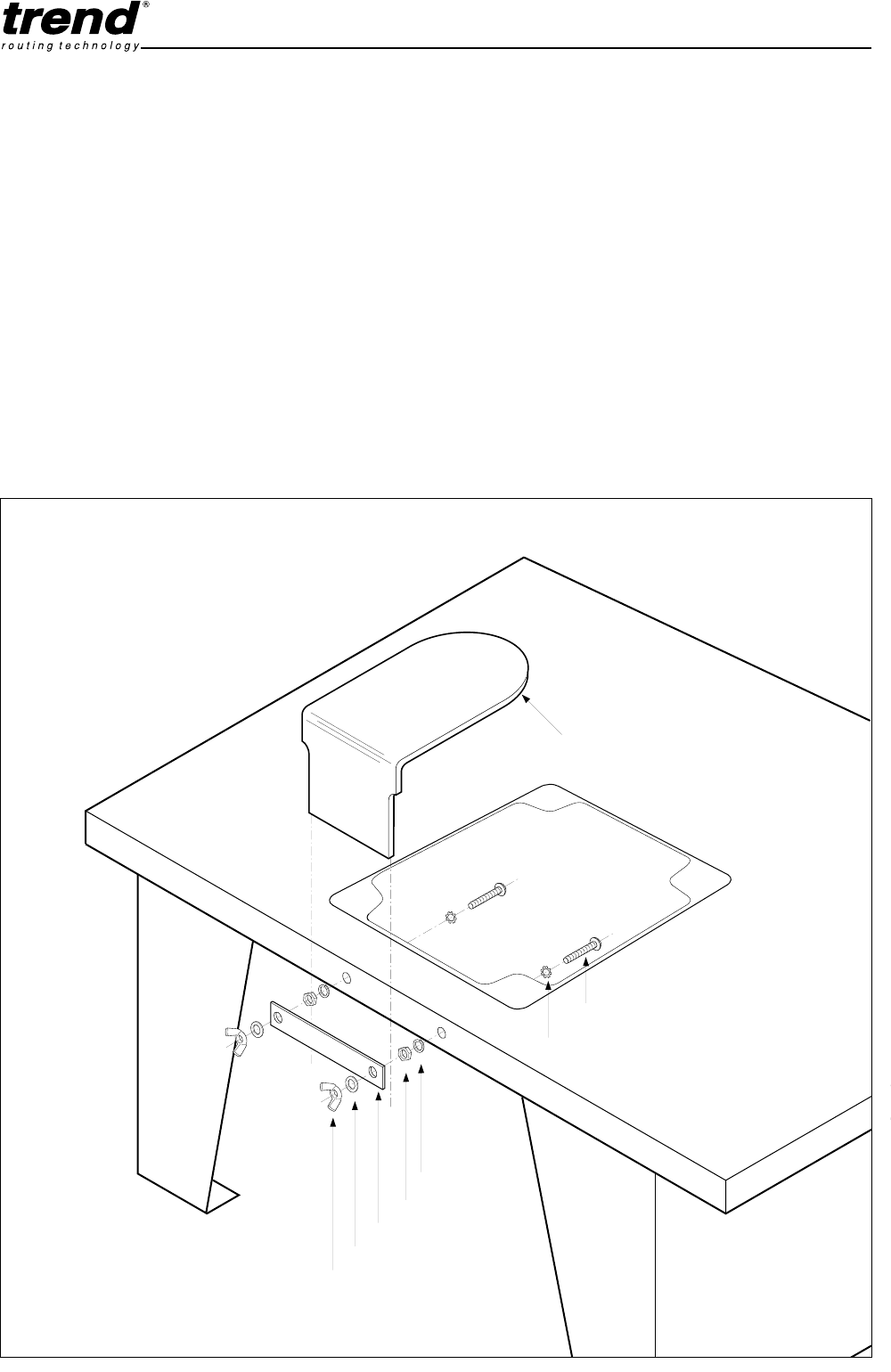
Assembly of Profiling Top Guard
The use of the optional accessory, Profiling Top Guard
is highly recommended to safely carry out the profiling of
workpieces with a bearing guided cutter. It will prevent
the operator's fingers inadvertantly contacting the cutter.
1.
Fit the Bolt, Star Washer, Spring Washer and Nut
in the sequence as indicated below.
2.
Tighten nut securely with a 8mm spanner.
3.
Fit Plate, Washer and Wing Nut.
4.
Slide the Perspex Guard in between the Plate and
edge of Table Surface.
5.
Gently tighten Wing Nuts.
Adjustment
1.
The height of the Perspex Guard should be
adjusted to leave a 6mm to 12mm gap between the
top of the workpiece and the underside of the
guard. This will prevent fingers coming into contact
with the cutter.
2.
To adjust the height undo the wing nuts, re-position
the guard and retighten.
Section Y describes a typical application involving the
use of bearing guided cutters with the Router Table.
fig. T
Wing Nut
Washer
Plate
Half Nut
Spring Washer
Star Washer
Perspex Guard
M5 Bolt
Profiling Top Guard - CRT/2