
Manual


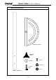

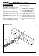

Table Of Contents
- THE ROUTER TABLE
- ASSEMBLY INSTRUCTIONS
- Assembly of legs
- Mounting Table to Workbench or Workboard
- Mounting Table to a Workmate
- Identification of Mounting Holes and Screws
- Re-Drilling of Router Base
- Re-Drilling of Insert Plate
- Re-Drilling of Insert Plate and Router base
- Fitting Insert Plate to Table Surface
- Fitting Router to Insert Plate
- Selecting & Fitting Insert Plate Rings
- Fitting Lead-on Pin
- Assembly & Mounting of Tenon Push Block
- Assembly of Safety Dust Guard to Back Fence
- Assembly of Back Fence
- Attachment of Back Fence to Table
- Assembly & Alignment of Mitre Fence
- Fitting of No-Volt Release Switch
- OPTIONAL ACCESSORIES
- OPERATION
- APPENDIX
Router Table for the Craftsman
-19-
T.
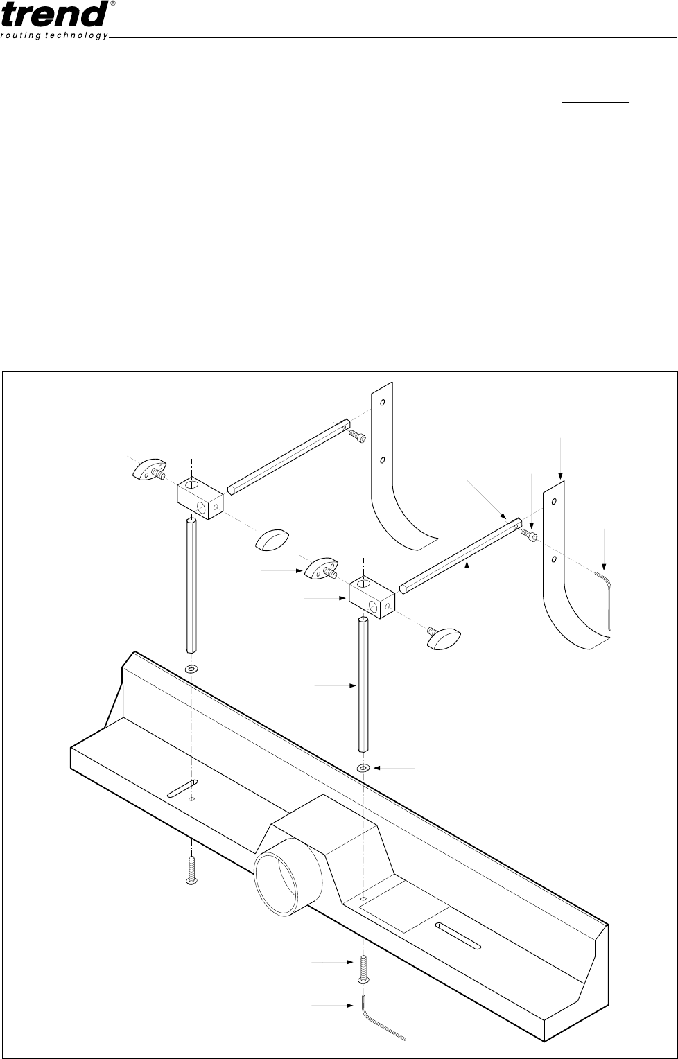
Assembly of Spring Pressure Clamps
The Optional Spring Pressure Clamps can be mounted
to the Back Fence. When adjusted to suit the width and
thickness of the material, it ensures the material is held
down onto the surface to obtain accurate machining of
the workpiece.
The Back Fence is pre-drilled to accept both Spring
Pressure Clamps.
1.
Remove Back Fence from Table Surface
2.
Insert Vertical Pillar Bolt through the underside of
the Back Fence.
3.
Fit washer and screw on the Vertical Pillar. Tighten
screw securely to ensure pillar is vertical.
4.
Fit knobs to Connector Block and slide it onto
Vertical Pillar.
5.
Slide Horizontal Bar through Connector Block.
fig. S
Vertical
Pillar Bolt
Vertical
Bar
Connector
Block
Knob
Washer
Horizontal
Bar
Retaining
Screw
Pressure
Strip
3mm
Allen
Key
4mm
Allen Key
Slot
Spring Pressure Clamp Set - CRT/10
6.
Slide Pressure Strip into the slot in Horizontal Bar
aligning the holes. Insert the Retaining Screw
ensuring it goes in through the un-threaded side of
the hole first.
Before tightening the Vertical Pillar Bolts, ensure that
the Vertical Pillar will allow the block to be positioned
parallel to the Back Fence with the knob engaging on the
flat of the Vertical Pillar.
Adjustment
The Spring Pressure Clamps will require adjusting to
suit the height and width of material being routed. The
Pressure Strips should provide enough pressure to
prevent the material lifting from the Table Surface, but
not too much as to create friction which would prevent the
material from sliding freely. The block assembly with
Horizontal Bar and Pressure Strip can be removed
from the Vertical Pillars when not required. The Vertical
Pillars can be left in position and will not impede the
Tenon Push Block system.