Operator’s Manual CompuCarve™ System Model Number: 133.217540 Please save this manual for future reference. CAUTION: Read and follow all Safety Rules and Operating Instructions before using this product. Sears, Roebuck and Co.
Introduction The CompuCarve™ System, with its computer-controlled 3D carving and general woodworking capabilities, is a revolutionary breakthrough in bench-top power tool design. This manual will explain the many features of the CompuCarve machine to help make creative carving operations pleasant and rewarding. Safety, performance, and dependability have been given top priority in the design of the CompuCarve System.
Table of Contents INTRODUCTION..................................................................................................I TABLE OF CONTENTS .................................................................................... II SPECIFICATIONS............................................................................................... 3 SAFETY................................................................................................................. 4 ELECTRICAL CONNECTIONS ...................
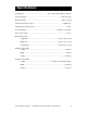
Specifications Package Size……………………………………… ….28.5” Long x 20.25” Wide x 18” Deep Package Weight………………………………………………………..………..78 lbs (35.4 kg) Machine Weight………………………………………………………..………...70 lbs (31.8 kg) Cut Motor Speed (No Load)………………………………………………………..20,000 rpm Cut Motor Horsepower (Peak)……………………………………………………………1.0Hp Electrical Rating………………………………………………………...110VAC at 8 A, 60 HZ Power Cord Length………………………………………………………………………...6 feet Movement Velocity: Length Axis……………………………………………………..
Safety CAUTION: Read and follow all Safety Rules and Operating Instructions before using this product. General Safety Rules For Power Tools ALWAYS WEAR EYE PROTECTION. The operation of any power tool can result in foreign objects being thrown into the eyes, which can result in severe injury. Before beginning tool operation, always wear safety goggles or safety glasses with side shields and a fullface shield when needed.
• DO NOT USE IN DANGEROUS ENVIRONMENT. Do not use power tools near gasoline or other flammable liquids or explosive fumes. Do not use in damp or wet conditions. • WEAR A DUST MASK to keep from inhaling fine particles. Use wood dust collection systems whenever possible. • NEVER LEAVE A RUNNING TOOL UNATTENDED. Turn the power off and do not leave the tool until it comes to a complete stop. • USE THE PROPER EXTENSION CORD. Make sure the extension cord is in good condition.
• KEEP HANDS AWAY FROM CUTTING AREA. When the machine is running, never reach underneath the workpiece or into the blade-cutting path for any reason. • DO NOT PLACE HANDS ON THE GRIT SURFACE DRIVE BELTS DURING OPERATION. Belts in motion could drag a hand into the machine and cause injury. • AVOID AWKWARD OPERATIONS AND HAND POSITIONS where a sudden slip could cause hands to move into the cutting area. • NEVER OPERATE THE MACHINE WITHOUT THE MUFFLER BAG IN PLACE.
To reduce exposure to these chemicals: • Work in a well ventilated area • Work with approved safety equipment, such as dust masks that are specially designed to filter out microscopic particles • Keep the machine and work area clean IMPORTANT NOTE: Servicing requires much care and specialized knowledge of the system and should be performed only by a qualified service technician. For service, return the machine to the nearest repair center in the original packaging.
Glossary Bevel Cut - A cut made across a workpiece that results in an angle other than 90˚ to the table surface. Cross Cut - A cutting operation across the grain or width of the workpiece. Head Screw - The threaded shaft on each side of the machine by which the head is raised and lowered when activated by the head crank. Joint or Jointing - A trim cut parallel to the grain of the wood on the edges of a board to create 90-degree angle with the top and bottom surface.
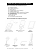
Unpacking the CompuCarve Machine Items included with the CompuCarve System A) B) C) D) E) F) G) H) I) J) K) CompuCarve Machine CarveWright Software CD Operation Manual CarveWright Memory Card Programmer CarveWright Memory Card 1/16” Diameter Tip Tapered Carving Bit with Bit Adapter 1/8” Diameter Straight Cutting Bit with Bit Adapter 3/32” Allen Wrench Muffler Dust Collector Bit removal Tool Crank Handle Ball and Shoulder Bolt Items Included With the CompuCarve System FIGURE 1: CARVEWRIGHT MEMORY CARD PRO
Unpacking and Setting Up the CompuCarve System 1. Remove the top packaging foam: After opening the shipping box, carefully remove the top molded foam packing from the machine. Located in the top tray are items B through K listed above. 2. Remove the machine from box: With a helper, lift out the machine and place it on a sturdy table or bench. Fold down the Outfeed Support Tables. Remove the plastic film covering the top clear safety cover. 3.
End Of Flexshaft Assembly Shaft Receptacle Ball Detent FIGURE 9: INSERTING THE FLEXSHAFT 6. Prepare cutting bits: The 1/16” Tapered carving Bit and the 1/8” Cutting bit will come assembled into the bit adapters. The setscrews will be secured with permanent thread cement. Do not attempt to loosen as the hex socket on the setscrew will likely strip. To replace a broken bit or to mount other purchased un-assembled bits, please see the section titled Bit Adapter Assembly in this manual. 7.
Hardware Features The key features of the CompuCarve multi-purpose tool and their locations are shown in the following illustrations.
HARDWARE FEATURES (cont.) Flexshaft Air Intake Cutting Motor Squaring Plate Muffler and Dust Collector Bag Sliding Guide Plate Folding Outfeed Table (rear) Outfeed Table Height Adjustment FIGURE 11: FEATURES - REAR VIEW Top Compression Rollers Board Edge Sensor Sears, Roebuck and Co. FIGURE 12: FEATURES, VIEW FROM BELOW (OUTFEED TABLE NOT SHOWN FOR CLARITY) CompuCarve™ System (Rev 1.
HARDWARE FEATURES (cont.) Vertical Moving Truck (Z-Truck) Y-Truck Guide Rails Horizontal Moving Truck (Y-Truck) Z-Truck Guide Rails FIGURE 13: CUTTING HEAD ASSEMBLY Far Overhead View of Machine (with workpiece) Z-Axis is up/down Right Workpiece Far-side Left Y-Axis Also referred to as the Front of the machine. This corner (near left) of the workpiece is the coordinate origin for all board measurements Near Keypad X-Axis FIGURE 14: DIRECTIONAL CONVENTIONS Sears, Roebuck and Co.
Operation Using the CompuCarve System Before the CompuCarve can begin to function, the CarveWright memory card must be installed. With the power off, push the memory card gently into the memory card slot until it stops, making sure the label is up. WARNING: Never remove the memory card from the machine while it is on. Doing so can result in damage to the workpiece. At any point during operation the CompuCarve machine can be stopped by pressing the STOP key or by lifting the cover.
Navigating the Menus Via the Keypad and LCD For input and display of information the CompuCarve machine employs a tactile keypad and LCD display. All operations require the user to input information at the actual machine location via the keypad (as opposed to information input and passed through the design software). The amount of information needed is dependent on the operation requested. The layout of the keypad is shown below.
Keypad Data Entry When a menu option asks for numerical data, such as length or depth dimensions, the keypad is used to enter the data. When fractional values are involved, data may be entered as either decimals or fractions. Decimals are the simplest. To enter a decimal simply type the whole number then the decimal point (down-arrow key) followed by the decimal part (i.e. 12.345). Fractions are entered simply by placing the ‘/’ (located on the up-arrow key) between the numerator and denominator.
WARNING: From the standpoint of safety, machine longevity, and output quality, it is important to follow all instructions concerning the proper bit to be used for each built-in function. For approved router bits, visit the CarveWright website. Rip or Cross Cut This function is provided to allow a board to be sized by width and/or length. A Rip Cut (along the grain or long axis) will size a board to the desired width; a Cross Cut (across the grain or narrow axis) will size a board to the desired length.
If there is a significant crown to the board, place the highest point of the crown under the cutting head. This will allow the machine to measure the highest point of the crown and will prevent the machine from taking and excessive cut. Use the Repeat shortcut key as many times as necessary to eliminate the crown. WARNING: Use only a 3/8” straight bit for jointing or squaring. Any other bit can cause damage to the workpiece or machine and can result in serious injury.
Measuring a Board The Measure Board function allows the user to measure the width or length of an existing board. Simply load a board in the typical way and press the ‘7’ (Measure) key on the keypad or use the up/down arrows to navigate from the main menu. The display will then ask for the direction the user wishes to measure. Configuration Menu Options The configuration menu allows the user to set project and machine settings as well as access important run-time and serial number data.
Carving a Project A project is a set of related design elements (patterns or figures) created with the CarveWright design software and stored on the memory card. These stored projects are accessed from the keypad. Simply press the ‘1’ (Projects) shortcut key to open the Projects Menu which can then be browsed using the up and down arrows. Once located, the desired project can be selected by pressing ENTER.
Inserting a Board Proper installation of the workpiece is critical to the performance and continued operation of the machine. To properly insert a workpiece: 1. Press down on the sliding guide plate release lever and move the sliding guide plate to the right so that it will clear the width of the workpiece. 2. Check the bottom of the workpiece for features that will make it unusable in the machine.
Sliding Guide Plate Traction Drive Sliding Guide Plate Release Lever Squaring Plate Board Tracking Sensor Board Sensor Detail FIGURE 19: WORKPIECE INSERTION DETAILS Release Lever Detail 6. At this point it is critical to assure that the workpiece can travel freely in and out of the machine along its entire length without binding or encountering significant drag. Do this by moving the workpiece in and out of the machine by hand while it is lying flat on the traction drive.
The clutch is intended to load the board against the traction drive with consistent force. In certain cases the machine can sense if the workpiece is not loaded enough and repeatably display “Please Load Board” on the LCD. Most often this decreased loading is caused by insufficient lubrication of the four vertical corner posts or the two vertical leadscrews. Please see the Checking the Head Pressure in the troubleshooting section for the proper lubrication procedure. 8.
Workpiece Preparation Before carving can begin a number of menu prompts and machine operations must be navigated. The machine will ask if the workpiece is to Stay Under Rollers. Keeping the workpiece under the top rollers is a way of avoiding undesirable snipe in the cut and maintaining contact with the Board Tracking Sensor at all times.
If possible, measure the workpiece to carve before starting the project layout in the software. This will help guide the design and prevent unintended scaling issues if the project design is different then the available workpiece. Measuring it with the machine will be the most accurate way. If the inserted workpiece is larger than the project design then the available options are: Keep Original Size, Scale the project to fit the workpiece, or Load New Board.
Jogging the Cutting Truck As described above, the machine offers several options for positioning the carving on the workpiece, one of which is “Jog to Position.” This is accomplished using the up and down arrows on the keypad to move the cutting truck across the width of the workpiece (near to far), and the left and right arrows will move the workpiece along its length (left or right). This option allows the user to place a carving at some location on a workpiece other than center or left corner.
When Auto-Jig is selected, the machine will prompt for a workpiece that is slightly wider or longer than the project's dimensions in order to prevent interference with the machine's mechanics. When the project is complete the machine can cut off the extra material if desired. WARNING: Whenever using the 1/8” cutting bit, it is strongly reccomended that the Stay Under Rollers option be set to Yes.
Bit Adapter Assembly The CompuCarve utilizes a patented quick release chuck system to make changing bits fast and easy. To use this system the bits must first be installed into the bit adapters. We recommend that each 1/4" bit used in the machine have its own dedicated adapter since the setscrews are required to be thread cemented. Swapping adapters will lead to stripped setscrews. In the case that the bit needs to be replaced, apply heat to the setscrews first to soften the thread cement before loosening.
Proper Bit Installation Into the Bit Adapter 1/2" Adapter Style – Assemble the bit so that the face of the adapter is 1/8” from the bottom of the cutting surface. FIGURE 24: CORRECT BIT ASSEMBLY IS SHOWN IN EXAMPLE A. THE BIT IS TOO LOW IN EXAMPLE B AND TWO HIGH IN EXAMPLE C. A (Correct) B (Incorrect) C (Incorrect) 1/4" Adapter Style – Like the 1/2" style, assemble the bit so that the face of the adapter is 1/8” from the bottom of the cutting surface.
BCT125 BCR062 BVG60 BVG90 J0002 BRD25 BRD50 BRO125 BRO188 BBN25 BBN50 BCO375 BCO50 CarveWright Approved Bits A B C D E F G H I J K L M # A B C D E F G H I J K L M Bit Name 1/8” Straight Cutting 1/16” Tapered Carving 60o V-Groove 90o V-Groove 3/8" Straight - Jointing 1/4" Round-Over 1/2" Round-Over 1/8” Roman Ogee 3/16" Roman Ogee 1/4" Ball Nose 1/2" Ball Nose 3/8” Classical Ogee 1/2" Classical Ogee Shank 1/4" 1/4" 1/4" 1/4" 1/2" 1/2" 1/2" 1/4" 1/2" 1/4" 1/4" 1/4" 1/2" LHR P/N B
Cocking the Quick Release Chuck The quick release chuck must be cocked in order to install a bit. To cock the chuck, press up on the chuck release flange (See Figure 28) located on the cap and release. The cap will rotate slightly in the counterclockwise direction as well and will remain up when the chuck is prepared to receive the bit assembly. Any time difficulty is encountered inserting a bit and adapter simply pull up on the flange to insure the chuck is cocked.
Bit Assembly Removal To remove a bit quickly, a thumb should be placed on the Z-Truck Grip Ridge (see Figure 28 below) and the Chuck Release Flange should be pulled up while pulling lightly on the bit with the opposite, gloved hand. WARNING: Use caution to avoid being cut by the sharp cutting edges of the router bit. Use caution if the bit has recently been in use; it may be HOT and a glove will be required to handle it.
Care and Maintenance The CompuCarve is a precision machine tool. With proper care and maintenance it will provide long, reliable service. WARNING: Always unplug machine before attempting any troubleshooting or maintenance on the machine. • Dust Removal: The CompuCarve is designed to tolerate a considerable amount of carving system dust, but to ensure proper operation it should be kept free of debris as much as possible. Periodically blow or vacuum out any dust or debris from the recesses of the unit.
o The patented quick release chuck’s operation can be affected by rust. Surface rust can cause the bit adapters to stick in the chuck. Periodically clean out dust from the chuck using compressed air and/or a small stiff bristled brush. Once cleaned, re-lubricate the chuck with multi-purpose light oil (like 3-IN-ONE oil).
General Tips and Helpful Reminders MAXIMUM CUT DEPTH for any operation is 1.0 inch. The machine will not allow deeper operations. ALL MOTORS ARE DISABLED when the front safety cover is open. The cover must be closed before the machine can proceed. WHEN LOADING THE WORKPIECE, there are several critical checks to make before proceeding. o Do not attempt to load a workpiece that has a significant taper to the sides.
WHEN CARVING IN PLASTIC, there are several issues to keep in mind. o o o o o o o Carving plastics can be very hard on the machine if the proper material is not used of if the chips are not regularly removed from the machine. Only Polycarbonate or Cast Acrylic plastics are approved for use in this machine. Most other common plastics melt during cutting and will damage the machine if used. The maximum cut depth for plastics is 0.1 inches per pass.
BEFORE STARTING, note the orientation of the project as viewed on the computer screen as compared to the orientation of the project as it is being carved on the machine. This is important in the event that a specific orientation or location of the project on the material is desired. See Figure 17 and Figure 18 for a graphical representation of the screen and machine orientations. Also, raster carvings will be completed from the front to the back of the machine. Sears, Roebuck and Co.
Troubleshooting WARNING: Always unplug machine before attempting any troubleshooting or maintenance on the machine. • Checking the Board Sensor: There are several reasons why the machine will prompt the user to “Check the Board Sensor”. o There is dust obscuring the sensor. Please see the next section titled “Cleaning of the Board Sensor” for details on how to address this situation.
• Troubleshooting the Board Sensor If the board sensor error cannot be resolved by cleaning the sensor as outlined above, continue with the following troubleshooting steps. To check the status of the board edge sensor, go to the CarveWright Main Menu-Configuration-Sensor Check menu Use the arrow keys to find Board Roller on the bottom line of the display and press ENTER. Do the following checks: o Load a board lower the head and check the reading displayed on the LCD when the sensor is over the board.
• Calibrating Machine Offsets: The "Calibrate Offsets" function is a simple procedure to allow the user to fine-tune the CompuCarve machine for improved accuracy. To perform the offset calibration the following will be needed: - A board at least 2" wide by 10" long between 1/2" and 3/4" thick. - The CompuCarve branded 3/8" Jointing Bit (using a nonCompuCarve branded bit will affect accuracy). - The CompuCarve sensor calibration will vary slightly depending on the color and darkness of the material.
Head Top Compression Rollers FIGURE 33: HEAD SHOWING COMPRESSION ROLLERS Checking the head pressure is very easy using a standard bathroom scale. 1. Before starting, make sure that the sliding plate is moved all the way to the far side of the machine and is out of the way of the scale. 2. Place the scale on the traction drive exactly like a regular workpiece.
• Please Check Board Errors: This prompt is shown when the boardtracking sensor is having difficulty monitoring the position of the workpiece accurately. This sensor tracks the position of the workpiece as it travels in and out of the machine. A small brass wheel rides along the bottom side of the material and provides position information to the control system.
Checking The Machine’s Onboard Sensors The status of each of the machine’s onboard sensors can be accessed from the LCD screen and keypad for the purpose of troubleshooting. To access the Sensor Check menu simply select the “0” (Options) key at the CarveWright Main Menu or use the up/down arrows to locate the Configurations Menu and then press ENTER. Next, select the “7” (Measure) key or use the up/down arrows to locate the Sensor Check menu and then press ENTER.
Z Position State – Numerical Value (0.000) The Z position sensor monitors the relative position of the up-and-down motion of the cutting truck. To check this sensor move the cutting truck all the way to the top of its vertical travel and record the displayed numerical value. Now move the truck all the way to the bottom of its vertical travel and then back to the top. If the sensor is operating correctly the displayed value will match the one previously recorded. X Position State – Numerical Value (0.