
Instruction Manual


ENGLISH
8
Worklight (Fig. A)
The worklight
6
is activated when the trigger switch is
depressed, and will automatically turn off 20 seconds after
the trigger switch is released. If the trigger switch remains
depressed, the worklight will remainon.
NOTE: The worklight is for lighting the immediate work
surface and is not intended to be used as aflashlight.
Variable Speed Trigger and Forward/
Reverse Control Button (Fig. A)
The tool is turned on and off by pulling and releasing
the variable speed trigger
3
. The farther the trigger is
depressed, the higher the speed of the tool. Your tool is
equipped with a brake. The chuck will stop as soon as the
trigger switch is fullyreleased.
A forward/reverse control button
4
determines the
rotational direction of the tool and also serves as a
lock-offbutton.
• To select forward rotation (clockwise), release the trigger
and depress the forward/reverse control button on the
right side of thetool.
• To select reverse (counterclockwise), depress the
forward/reverse control button on the left side of
thetool.
NOTE: The center position of the control button locks the
tool in the off position. When changing the position of the
control button, be sure the trigger isreleased.
NOTE: Continuous use in variable speed range is not
recommended. It may damage the switch and should
beavoided.
NOTE: The first time the tool is run after changing the
direction of rotation, you may hear a click on start up. This is
normal and does not indicate aproblem.
Installing and Removing the Battery Pack
(Fig. C)
NOTE: For best results, make sure your battery pack is
fullycharged.
To install the battery pack
1
into the tool handle, align the
battery pack with the rails inside the tool’s handle and slide
it into the handle until the battery pack is firmly seated in
the tool and ensure that it does notdisengage.
To remove the battery pack from the tool, press the release
button
2
and firmly pull the battery pack out of the tool
handle. Insert it into the charger as described in the charger
section of thismanual.
OPERATION
WARNING: To reduce the risk of serious personal
injury, turn unit off and remove the battery pack
before making any adjustments or removing/
installing attachments or accessories. An
accidental start-up can causeinjury.
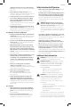
Fig.C
1
2
Fig.D
10
Fig.B
7
9
To install an accessory on the hog ring anvil, firmly push
accessory onto the anvil
7
. The hog ring
9
compresses
to allow the accessory to slide on. After accessory is
installed, the hog ring applies pressure to help provide
accessoryretention.
To remove an accessory, grasp the accessory and firmly
pull itoff.
Proper Hand Position (Fig. D)
WARNING: To reduce the risk of serious personal
injury, ALWAYS use proper hand position as shown.
WARNING: To reduce the risk of serious personal
injury, ALWAYS hold securely in anticipation of a
suddenreaction.
Proper hand position requires one hand on the main
handle
10
.