Operator’s Manual 10 IN. COMPACT SLIDE MITER SAW Model No. 137.407530 CAUTION: ● ● ● ● ● Before using this Miter Saw, read this manual and follow all its Safety Rules and Operating Instructions Customer Help Line For Technical Support 1-800-843-1682 Safety Instructions Assembly Operation Maintenance Parts List Sears Parts & Repair Center 1-800-488-1222 Sears Brands Management Corporation Hoffman Estates, IL 60179 USA See the full line of Craftsman® products at craftsman.
TABLE OF CONTENTS SECTION PAGE Warranty ................................................................................................................ 2 Product Specifications ........................................................................................... 3 Symbols.................................................................................................................. 4 Power Tool Safety ..................................................................................................
PRODUCT SPECIFICATIONS MOTOR: Power Source ........................................ Speed .................................................... Electric Brake ........................................ Double Insulated ................................... Arbor Shaft Size .................................... 120V AC, 60 Hz, 15 Amp 4800 RPM (No load) Yes Yes 5/8 in. BLADE: Diameter ................................................ 10 in. Arbor Hole ............................................. 5/8 in.
SYMBOLS WARNING ICONS Your power tool and its Operator’s Manual may contain “WARNING ICONS” (a picture symbol intended to alert you to, and/or instruct you how to avoid, a potentially hazardous condition). Understanding and heeding these symbols will help you operate your tool better and safer. Shown below are some of the symbols you may see. SAFETY ALERT: Precautions that involve your safety. PROHIBITION WEAR EYE PROTECTION: Always wear safety goggles or safety glasses with side shields.
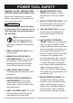
POWER TOOL SAFETY 7. MAKE WORKSHOP CHILD PROOF with padlocks, master switches or by removing starter keys. GENERAL SAFETY INSTRUCTIONS BEFORE USING THIS POWER TOOL Safety is a combination of common sense, staying alert and knowing how to use your power tool. ! 8. DO NOT FORCE THE TOOL. It will do the job better and safer at the rate for which it was designed. WARNING To avoid mistakes that could cause serious injury, do not plug the tool in until you have read and understood the following. 1. 9.
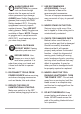
12. 13. 14. 17. USE RECOMMENDED ACCESSORIES. Consult this Operator’s Manual for recommended accessories. The use of improper accessories may cause risk of injury to yourself or others. ALWAYS WEAR EYE PROTECTION. Any power tool can throw foreign objects into the eyes and could cause permanent eye damage. ALWAYS wear Safety Goggles (not glasses) that comply with ANSI Safety standard Z87.1. Everyday eyeglasses have only impact– resistant lenses. They ARE NOT safety glasses.
22. MAINTAIN TOOLS WITH CARE. Keep tools sharp and clean for best and safest performance. Follow instructions for lubricating and changing accessories. 23. DO NOT use power tool in presence of flammable liquids or gases. 24. DO NOT operate the tool if you are under the influence of any drugs, alcohol or medicationn that could affect your ability to use the tool properly. 25. WARNING: Dust generated from certain materials can be hazardous to your health.
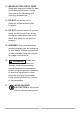
COMPOUND MITER SAW SAFETY SPECIFIC SAFETY INSTRUCTIONS FOR THIS COMPOUND MITER SAW 10. USE only blade collars specified for your saw. 1. DO NOT operate the miter saw until it is completely assembled and installed according to these instructions. 11. NEVER use blades larger in diameter than 10 inches. 12. NEVER apply lubricants to the blade when it is running. 2. IF YOU ARE NOT thoroughly familiar with the operation of miter saws, seek guidance from your supervisor, instructor or other qualified person.
21. NEVER cut small pieces. If the workpiece being cut would cause your hand or fingers to be within 7.5 in. of the saw blade the workpiece is too small. immediately. Be alert at all times - especially during repetitive, monotonous operations. Don’t be lulled into carelessness due to a false sense of security. Blades are extremely unforgiving. Clean the lower guard frequently to help visibility and movement. Unplug before adjustment or cleaning. 22.
ELECTRICAL REQUIREMENTS AND SAFETY POWER SUPPLY AND MOTOR SPECIFICATIONS To reduce the risk of electrical shock, this saw has a polarized plug (one blade is wider than the other). This plug will fit in a polarized outlet only one way. If the plug does not fit fully in the outlet, reverse the plug. If it still does not fit, contact a qualified electrician to install the proper outlet. Do not change the plug in any way. The AC motor used in this saw is a universal, nonreversible type.
Be sure your extension cord is properly wired and in good condition. Always replace a damaged extension cord or have it repaired by a qualified person before using it. Protect your extension cords from sharp objects, excessive heat and damp or wet areas. 3. If the tool suddenly stalls while cutting wood, release the trigger switch, unplug the tool, and free the blade from the wood. The saw may now be started and the cut finished. 4. FUSES may “blow” or circuit breakers may trip frequently if: a.
ACCESSORIES AND ATTACHMENTS always visually examine the blade and tips for bent blade, cracks, breakage, missing or loose tips, or other damage. Do not use if damage is suspected. Failure to heed safety instructions and warnings can result in serious bodily injury. RECOMMENDED ACCESSORIES ! WARNING ● Use only accessories recommended for this miter saw. Follow instructions that accompany accessories. Use of improper accessories may cause hazards. ● The use of any cutting tool except 10 in.
TOOLS NEEDED FOR ASSEMBLY Supplied Not supplied Blade Wrench Adjustable Wrench Phillips Screwdriver Combination Square Slotted Screwdriver COMBINATION SQUARE MUST BE TRUE Should not gap or overlap when square is flipped over (see dotted figure). Straight edge or a 3/4 in. board, this edge must be perfectly straight. Draw light line on board along this edge. Should not gap or overlap when square is flipped over (see dotted figure).
CARTON CONTENTS 2. Place the saw on a secure stationary work surface. 3. Separate all parts from the packing material. Check each one with the illustration to make certain all items are accounted for before discarding any packing material. UNPACKING YOUR MITER SAW ! WARNING To avoid injury from unexpected starting or electrical shock, do not plug the power cord into a source of power during unpacking and assembly. This cord must remain unplugged whenever you are working on the saw.
KNOW YOUR SLIDING COMPOUND MITER SAW ON/OFF Trigger Switch Handle Laser ON/OFF Switch Slide Carriage Lock Knob Cover Plate Motor Brush Cap Laser Vertical Adjustment Knob Laser Horizontal Adjustment Knob Slide Carriage Bevel Locking Handle Lower Blade Guard Hold-down Clamp Table Sliding Fence Left Extension Wing Stop Plate Laser Trac® Laser Guide Arbor Lock Button Blade Base Miter Detent Override Positive Stop Locking Lever Built-in Carry Handle (Lift unit here) Blade Wrench Storage Stop Knob H
GLOSSARY OF TERMS AMPERAGE (AMPS) – A measure of the flow of electric current. Higher ratings generally means the tool is suited for heavier use. FACE SHIELD – An impact resistant shield that helps to protect your face from chips, sparks, small debris. Should only be used in conjunction with additional eye protection. ARBOR LOCK – Allows the user to keep the blade from rotating while tightening or loosening the arbor bolt during blade replacement or removal.
POSITIVE STOP LOCKING LEVER – Locks the miter saw at a preset positive stop for the desired miter angle. KICKBACK – sudden and unintended movement of the tool or workpiece. It is typically caused by binding or pinching of the workpiece. SWITCH HANDLE – The switch handle contains the trigger switch and the laser on/off switch. The blade is lowered into the workpiece by pushing down on the handle. The saw will return to its upright position when the handle is released.
ASSEMBLY ! WARNING 1. Push the cutting head down. 2. Press the hold-down latch (2) in to lock. IMPORTANT: To avoid damage, never carry the miter saw by the trigger switch handle or the cutting arm. To avoid injury, do not connect this miter saw to the power source until it is completely assembled and adjusted and you have read and understood this Operator’s Manual. INSTALLING THE DUST BAG (FIG. B) 1. Install the dust bag assembly (1) onto the exhaust port (2) on the miter saw.
INSTALLING THE HOLD-DOWN CLAMP ASSEMBLY (FIG. E, F) Place the hold-down clamp assembly (1) in one of the mounting holes (2) located behind the fence. Fig. E INSTALLING THE MITER HANDLE (FIG. C) 1. Insert the miter handle (1) into the hole in front of the miter saw and align the hole (2) on the miter handle (1) with the hole (3) in the front of the table. 2. Thread the screw (4) through the hole (3) in the table into the hole (2) on the miter handle (1). 3. Tighten the screw (4) with a screwdriver.
REMOVING AND INSTALLING THE BLADE 7. Locate the arbor lock button (5) below the trigger switch handle. (Fig. I) 8. Press the arbor lock button (5), holding it in firmly while turning the blade wrench clockwise. This will engage the arbor lock allowing the arbor bolt to be loosened with the blade wrench. Continue to hold the arbor lock button (5), while turning the wrench clockwise to loosen the arbor bolt. ! WARNING ● Do not use a blade larger than 10 in. in diameter.
Installing the Blade (Fig. H, H-1, I, J) 1. Install a 10 in. blade with a 5/8 in. arbor hole making sure the rotation arrow on the blade matches the clockwise rotation arrow on the upper guard, and the blade teeth are pointing downward at the front of the saw. 2. Place the outer blade collar (6) against the blade and on the arbor. Thread the arbor bolt (4) onto the arbor in a anti-clockwise direction. (Fig. J) IMPORTANT: The flat side of the blade collar must be placed against the blade.
● To avoid injury from flying debris, do not allow visitors to stand behind the saw. ● Place the saw on a firm, level workbench where there is room for handling and properly supporting the workpiece. ● Support the saw on a level work surface. ● Bolt or clamp the saw to its support. 2. To install, reposition the table insert, install the six screws and tighten. 3. Check for blade clearance by moving the slide carriage through the full motion of the blade in the table slot. Fig.
2. For portable use, place the saw on a 3/4 in. thick piece of plywood. Bolt the base of the miter saw securely to the plywood using the mounting holes on the base. Use C-clamps to clamp this mounting board to a stable work surface at the worksite. (Fig. M) Fig. M 3/4 in. plywood NOTE: If a miter saw stand is used, please follow all instructions shown in that product’s instructions for proper mounting. THE POWER CORD STORAGE (FIG.
ADJUSTMENTS BEVEL STOP ADJUSTMENT 90° Bevel Pointer Adjustment (Fig. P) 1. When the blade is exactly 90° (0°) to the table, loosen the bevel indicator screw (1) using a Phillips screwdriver. 2. Adjust bevel indicator (2) to the “0” mark on the bevel scale and retighten the screw. ! WARNING To avoid injury from an accidental start, make sure the switch is in the OFF position and the plug is not connected to the power source outlet. 90° (0°) Bevel Adjustment (Fig. O) 1.
5. Tilt the cutting arm back to the left and recheck alignment. 6. Repeat above steps until the blade is 45° to the table. Once alignment is achieved, tighten the lock nut (5) to secure the bolt (6). the blade at the desired angle quickly and accurately. Follow the process below for quickest and most accurate adjustments. Adjusting Miter Angles: 1. Lift up on the quick-cam miter locking lever (1) to unlock the table. 2.
4. Adjust the fence 90° to the blade and tighten the four fence locking bolts (1). NOTE: If the saw has not been used recently, recheck blade squareness to the fence and readjust if needed. 5. After fence has been aligned, using a scrap piece of wood, make a cut at 90° then check squareness on the piece. Readjust if necessary. 3. Recheck the blade depth by moving the cutting head front to back through the full motion of a typical cut along the control arm. Fig. T 1 3 4 Fig.
Setting the cutting depth (Fig. T-1): The depth of cut can be preset for even and repetitive shallow cuts. 1. Adjust the cutting head down until the teeth of the blade are at the desired depth. 2. While holding the upper arm in that position, turn the stop knob (1) until it touches the stop plate (2). 3. Recheck the blade depth by moving the cutting head front to back through the full motion of a typical cut along the control arm. TABLE SUPPORT ROD ADJUSTMENT (FIG. U) 1. Put the miter saw on a flat surface.
! ● CAUTION: The use of optical instruments with this product will increase eye hazard. ● WARNING: Do not attempt to repair or disassemble the laser. If unqualified persons attempt to repair this laser product, serious injury may result. Any repair required on this laser product should be performed by an authorized service center personnel. WARNING Do not remove the lock from the ON/OFF switch during any laser adjustments. AVOID DIRECT EYE CONTACT (FIG.
Procedure B (Fig. X, Z) 2. Slightly turn the laser horizontal adjustment knob (2) to adjust the horizontal angle of laser beam on the top of the board. If the laser beam is out of parallel from left to right, turn the laser horizontal adjustment knob (2) clockwise; If the laser beam is out of parallel from right to left, turn the laser horizontal adjustment knob (2) anti-clockwise until the laser beam is parallel with the horizontal “pattern line”. 3. Recheck the laser beam alignment. 3.
REPETITIVE CUTTING USING THE STOP PLATE (FIG. AA) The stop plate is designed for making repetitive cuts of the same length. NOTE: Use only one stop plate at a time, NEVER use both stop plates. 1. Rotate the stop plate (3) to vertical position. 2. If stop plate will not rotate, loosen the locking screw (4) 1/4 turn using a screwdriver and 8 mm wrench. Fig. Z Anti-clockwise Clockwise Laser beam Pattern line EXTENSION WING USE AND ADJUSTMENT (FIG.
OPERATION SAFETY INSTRUCTIONS FOR BASIC SAW OPERATION BEFORE USING THE MITER SAW ! WARNING To avoid mistakes that could cause serious, permanent injury, do not plug the tool in until the following steps are completed: ● Completely assemble and adjust the saw, following the instructions. (ASSEMBLY & ADJUSTMENTS) ● Learn the use and function of the ON/OFF trigger switch, on/off switch for laser, upper and lower blade guards, head hold-down latch, bevel lock handle, and cover plate screw.
● To avoid injury from jams, slips, or thrown pieces, use only recommended accessories. ● Check the dust bag before you work. Empty the bag if it is more than half-full. ● Plan ahead to protect your eyes, hands, face and ears. ● Know your miter saw. Read and understand this Operator’s Manual and labels affixed to this tool. Learn its application and limitations as well as the specific potential hazards peculiar to this tool.
DRESS FOR SAFETY Any power tool can throw foreign objects into the eyes. This can result in permanent eye damage. Everyday eyeglasses have only impact resistant lenses and are not safety glasses. Glasses or goggles not in compliance with ANSI Z87.1 could seriously injure you when they break. ● Do not wear loose clothing, gloves, neckties or jewelry (rings, watches). They can get caught and draw you into moving parts. ● Wear non-slip footwear. ● Tie back long hair. ● Roll long sleeves above the elbow.
● When cutting odd shaped workpieces, plan your work so it will not bind in the blade and cause possible injury. Molding, for example, must lie flat or be held by a fixture or jig that will not let it move when cut. ● Properly support round material such as dowel rods, or tubing, which have a tendency to roll when cut, causing the blade to “bite”. ! MAKING A BASIC CUT ! Body and Hand Position (Fig. BB) Never place hands near the cutting area.
● If the blade doesn’t stop within 6 seconds, unplug the saw and follow the instructions in TROUBLESHOOTING GUIDE section. NOTE: To make the ON/OFF switch childproof. Insert a padlock (not provided), or chain with padlock, through the hole (2) in the trigger switch, locking the tool’s switch, preventing children and other unqualified users from turning the machine on. Before freeing jammed material: ● Release trigger switch. ● Wait for all moving parts to stop. ● Unplug the miter saw.
NOTE: When transporting the saw, always secure the sliding fence in the collapsed position and locking it. Removing 1. Unlock the fence cam locking lever (1) by pushing it out toward the rear of the machine. 2. Align the slot (2) with the bolt (3) in the rear of the fence, and then lift up the sliding fence to remove it from the saw. Fig. DD 2 Installing 1. Align the slot (2) with the bolt (3) in the rear of the fence to place the sliding fence onto the miter saw fence. 2.
NOTE: The quick-cam miter table lock should lock the table and prevent it from moving. If adjustment is needed, see the section of “QUICK-CAM MITER TABLE LOCK ADJUSTMENT”. 1. For chop cutting operations on small workpieces, slide the cutting head assembly completely toward the rear of the unit and tighten the sliding carriage lock knob (1). 2. To cut wide boards up to 12-1/2 in., the sliding carriage lock knob (1) must be loosened to allow the cutting head to slide freely. Fig. GG 1 3 Fig.
left and right. These locations represent the most common angles for cutting operation. To make a miter cut: 1. Unlock the miter table by lifting up on the quick-cam miter locking lever (2). 2. While raising the positive stop locking lever (3) up, grasp the miter handle (4) and rotate the miter table left or right to the desired angle. 3. Release the positive stop locking lever and set the miter at the desired angle making sure the lever snaps into place.
BEVEL CUT (FIG. JJ) ! Fig. JJ 2 WARNING ● The sliding fence must be extended to the left when making bevel cuts. The sliding fences note three bevel angles where the user must adjust the fences to match the degree of the bevel cut. Failure to extend the sliding fence will not allow enough space for the blade to pass through which could result in serious injury. At extreme miter or bevel angles the saw blade may also contact the fence.
To Slide Cut Wide Boards (Fig. MM) 1. Unlock the sliding carriage lock knob (1) and allow the cutting head assembly to move freely. 2. Set both the desired bevel angle and/or the miter angle and lock into position. 3. Use a hold-down clamp to secure the workpiece. 4. Turn the laser guide on and position the workpiece on the table for prealignment of your cut. 5. Grasp the trigger switch handle (2) and pull the carriage (3) forward until the center of the saw blade is over the front of the workpiece (4). 6.
CUTTING GROOVES (FIG. OO) CUTTING BOWED MATERIAL (FIG. NN) ! ! WARNING WARNING DO NOT USE A DADO BLADE, use only the standard 10 in. diameter saw blade for this operation. 1. Mark lines identifying the width and depth of the desired cut on the workpiece and position on the table so the outside tip of the blade is positioned on the inside edge of the line. Use a clamp to secure the workpiece beside the blade. 2.
CUTTING BASE MOLDING (FIG. QQ) Base moldings and many other moldings can be cut on a compound miter saw. The setup of the saw depends on molding characteristics and application, as shown. Perform practice cuts on scrap material to achieve best results: 1. Always make sure moldings rest firmly against fence and table. Use hold-down, crown molding vice or C-clamps, whenever possible, and place tape on the area being clamped to avoid marks. 2. Reduce splintering by taping the cut area prior to making the cut.
CUTTING CROWN MOLDING (FIG. RR, SS) Your compound miter saw is suited for the difficult task of cutting crown molding. To fit properly, crown molding must be compound-mitered with extreme accuracy. The two surfaces on a piece of crown molding that fit flat against the ceiling and wall are at angles that, when added together, equal exactly 90°. Fig. RR F e n c e Workpiece Miter saw table Fig.
NOTE: The chart below references a compound cut for crown molding ONLY WHEN THE ANGLE BETWEEN THE WALLS EQUALS EXACTLY 90°. KEY BEVEL SETTING MITER SETTING TYPE OF CUT Inside corner - Left side IL 33.9° 1. Position top of molding against fence. 31.6° Right 2. Miter table set at RIGHT 31.6°. 3. LEFT side is finished piece. Inside corner - Right side IR 33.9° 31.6° Left 1. Position bottom of molding against fence. 2. Miter table set at LEFT 31.6°. 3. LEFT side is finished piece.
CROWN MOLDING CHART Compound Miter saw Miter and Bevel Angle Settings Wall to Crown Molding Angle Angle Between Walls 67 68 69 70 71 72 73 74 75 76 77 78 79 80 81 82 83 84 85 86 87 88 89 90 91 92 93 94 95 96 97 98 99 100 101 102 103 104 105 106 107 108 109 110 111 112 113 114 115 116 117 118 119 120 121 122 123 52/38° Crown Molding 45/45° Crown Molding Miter Setting Bevel Setting Miter Setting Bevel Setting 42.93 42.39 41.85 41.32 40.79 40.28 39.76 39.25 38.74 38.24 37.74 37.24 36.75 36.27 35.79 35.
MAINTENANCE MAINTENANCE into. Tighten the cap snugly, but do not overtighten. Repeat for the carbon brush located on the other side of motor. NOTE: To reinstall the same brushes, first make sure the brushes go back in the way they came out. This will avoid a break-in period that reduces motor performance and increases wear. ! DANGER To avoid injury, never put lubricants on the blade while it is spinning.
SAWDUST Periodically, sawdust will accumulate under the work table and base. This could cause difficulty in the movement of the worktable when setting up a miter cut. Frequently blow out or vacuum up the sawdust. Central pivot of plastic guard: Use light household oil (sewing machine oil) on metal-to-metal or metal-to-plastic guard contact areas as required for smooth, quiet operation. Avoid excessive oil, to which sawdust will cling.
TROUBLESHOOTING GUIDE ! WARNING To avoid injury from accidental starting, always turn switch OFF and unplug the tool before moving, replacing the blade or making adjustments. TROUBLESHOOTING GUIDE - MOTOR PROBLEM SUGGESTED CORRECTIVE ACTION PROBLEM CAUSE Brake does 1. Motor brushes not sealed or not stop lightly sticking. blade within 2. Motor brake overheated 6 seconds. from use of defective or wrong size blade or rapid ON/OFF cycling. 3. Arbor bolt loose. 4. Brushes cracked, damaged, etc. 5. Other.
TROUBLESHOOTING GUIDE - SAW OPERATION PROBLEM Blade hits table. PROBLEM CAUSE SUGGESTED CORRECTIVE ACTION 1. See ADJUSTMENT- CUTTING ARM TRAVEL section. 1. Misalignment. Angle of cut not 1. Miter table unlocked. 1. See OPERATION - MITER ANGLE ADJUSTMENT section. accurate. Can not 2. Sawdust under table. 2. Vacuum or blow out dust. WEAR adjust miter. EYE PROTECTION. Cutting arm wobbles. 1. Loose pivot points. Cutting arm will 1.
PARTS LIST 10 IN. COMPACT SLIDE MITER SAW ! MODEL NO. 137.407530 WARNING When servicing use only CRAFTSMAN replacement parts. Use of any other parts many create a HAZARD or cause product damage. Any attempt to repair or replace electrical parts on this Miter Saw may create a HAZARD unless repair is done by a qualified service technician. Repair service is available at your nearest Sears Service Center. PARTS LIST FOR MITER SAW (A) I.D. Description Size Q’ty I.D. Description Size 1 0K74 CR. RE.
10 IN. COMPACT SLIDE MITER SAW PARTS LIST FOR MITER SAW (B) I.D. 262V 26LU 27PQ 2840 290M 2B7H 2BLQ 2BQA 2D7E 2D92 2DWP 2F39 2JAP 2K96 2MC3 2MMC 2N7W 2NAH 2QM7 2S45 2T9B 2VEP 2VH6 2VN7 2VS0 2VZ1 2WPX 2WUT 2YR6 31VX 31XE 349F 349G 34BN 34DK 34HH 34NJ 34NK 35CH 35QJ 3BKA 3BKB 3BKC 3BKD 3BMZ 3BN0 3CBQ 3CBR 3CD5 3CD6 3DHP 3DJ8 3DJ9 3DJA 3DJG 3DJH 3DJL 3DJP 3DJR Description ANCHOR PLATE WARNING LABEL ROLL PIN COMPRESSION SPRING CAUTION LABEL HEX. SOC. SET SCREW HEX. SOC. HD.
10 IN. COMPACT SLIDE MITER SAW SCHEMATIC MODEL NO. 137.
10 IN. COMPACT SLIDE MITER SAW PARTS LIST FOR MOTOR MODEL NO. 137.407530 I.D. Description 0HX9 NEEDLE BEARING Size Q’ty 0JCD SPRING PIN 0JX2 HEX. SOC. SET SCREW M5*0.8-6 2 0K43 CR. RE. PAN HD. SCREW & WASHER M5*0.8-16 2 0K44 CR. RE. PAN HD. SCREW & WASHER M5*0.8-12 1 0KBC CR. RE. PAN HD. TAPPING SCREW M5*16-25 2 0KCP CR. RE.
REPAIR PROTECTION AGREEMENTS Congratulations on making a smart purchase. Your new Craftsman® product is designed and manufactured for years of dependable operation. But like all products, it may require repair from time to time. That’s when having a Repair Protection Agreement can save you money and aggravation.
NOTES 55