
User's Manual

DR-915L OEM DATA RADIO MODULE
___________________________________________________________________________________________
Revision I INTEGRATOR’S GUIDE
15
DR-915L DATA RADIO
HARDWARE INTERFACE
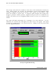
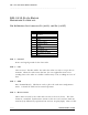
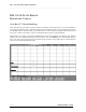
Pin Definitions for Connector P2 (915L) and P4 (915LT)
PIN
FUNCTION
1 Ground
2 CTS
3 DTR
4 Receive Data
5 Transmit Data
6 Reset
7 SPI Clock
8 SPI MISO/Fail
9 SPI MOSI/Sending
10 VCC
PIN 1 – Ground
Power and signal ground for the data radio.
PIN 2 – CTS
Clear to Send. This line will be low when the radio is ready to accept data to
transmit. When the radio raises this line, the user application must cease
sending data to the radio or a buffer overflow may occur, resulting in a loss of
data.
PIN 3 – DTR
Data Terminal Ready. This line is used to place the radio into configuration
mode. It should be held low for normal operation.
PIN 4 – Receive Data
This is data received by the radio and sent out to the user device. The data
format is a standard, asynchronous stream at the user-set baud rate with one
start bit (low) followed by eight data bits and one stop bit (high). This is a TTL-