CDR-9150 Data Radio Module INTEGRATOR’S GUIDE Coyote DataCom, Inc. 12721 Benson, Overland Park, KS 66213 • Tel. 913-685-8350 • Fax 913-685-0732 www.coyotedatacom.com • sales@coyotedatacom.
CDR-9150 OEM DATA RADIO MODULE ___________________________________________________________________________________________ TABLE OF CONTENTS General Information and Labeling Requirements.....................................3 FCC RF Exposure Statement ..................................................................4 Configuration........................................................................................6 Specifications..........................................................................
CDR-9150 OEM DATA RADIO MODULE ___________________________________________________________________________________________ CDR-9150 Data Radio General Information and Labeling Requirements This CDR-9150 is a frequency-hopping spread spectrum data transceiver operating in the 902-928 MHz ISM band. The unit is designed to operate under Part 15.247 of the FCC rules and regulations and is designed as an OEM module for integration into other products or field devices.
CDR-9150 OEM DATA RADIO MODULE ___________________________________________________________________________________________ CDR-9150 D ATA R ADIO R EGULATORY FCC RF Exposure Statement This device complies with FCC radiation exposure limits as set forth for an uncontrolled environment. When using the antennas listed below, this device should be installed and operated with a minimum separation distance of 20 cm between the radiator and your body.
CDR-9150 OEM DATA RADIO MODULE ___________________________________________________________________________________________ CDR-9150 D ATA R ADIO C ONFIGURATION Default Settings Serial Baud ............................................................................. 9600 bits/second Port......................................................................................................... UART RX buffer size ..................................................................................
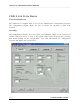
CDR-9150 OEM DATA RADIO MODULE ___________________________________________________________________________________________ CDR-9150 D ATA R ADIO C ONFIGURATION The CDR-9150 is supplied with an easy-to-use Windows98™ configuration program. The configuration program allows the user to control the operation of their radio network. Installing The configuration software does not require an installation. Simply run it from the CD labeled “CDR-9150 Tools” or copy it onto another drive.
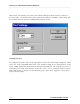
CDR-9150 OEM DATA RADIO MODULE ___________________________________________________________________________________________ Click on the “PC Settings” tab, then select which COM port will be used to connect to the data radio. As shown below, ports COM1 thru COM4 are available. This setting will be retained the next time the configuration program is run. Getting Started To configure the radio, click on the appropriate tab for the radio being configured. Then select the radio Communications Port.
CDR-9150 OEM DATA RADIO MODULE ___________________________________________________________________________________________ CDR-9150 Repeater Revision B INTEGRATOR’S GUIDE 8
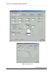
CDR-9150 OEM DATA RADIO MODULE ___________________________________________________________________________________________ Addressing The radio has been designed to be very versatile in its addressing functions. Each radio has its own identifier consisting of a group number and address number. The Source Group specifies which group of radios the unit being configured belongs to. The Source Address specifies the address within that group that uniquely identifies this radio.
CDR-9150 OEM DATA RADIO MODULE ___________________________________________________________________________________________ Number of Repeaters The range of the CDR-9150 may be extended by using repeaters. Repeater modules receive data packets on one group code and retransmit the packet on another group code.
CDR-9150 OEM DATA RADIO MODULE ___________________________________________________________________________________________ Path Management The CDR-9150 has powerful path management tools to help ensure successful field installations. The Path Management window has two modes, Continuous and On-Sync. The Continuous mode allows the installer to look at competing signals on the radio’s channel and determine if there is a potential interference problem.
CDR-9150 OEM DATA RADIO MODULE ___________________________________________________________________________________________ The On-Sync mode allows the installer to look only at radio transmissions for CDR-9150 radios. When packets are received, the transmission’s current and maximum signal strength is displayed along with the packet’s source group code and address. This allows the installer to ensure there is adequate signal strength with enough fade margin to guarantee reliable operation.
CDR-9150 OEM DATA RADIO MODULE ___________________________________________________________________________________________ Code Upgrading The CDR-9150 has been designed for easy field upgrades. Using the RS-232 Serial Adapter board, a DR915 Programming cable, a standard Serial Configuration cable and a current version of the CDR-9150 Configuration program running on the user’s PC, the radio can be re-flashed with new operating code. Special customer code can also be loaded in this manner.
CDR-9150 OEM DATA RADIO MODULE ___________________________________________________________________________________________ CDR-9150 Data Radio S PECIFICATIONS Overall Frequency .................................................................................... 902-928 MHz Frequency Control..................................................................... PLL Synthesizer Transport ...............................................Transparent, Point-to-Point Guaranteed Data Interface .......................
CDR-9150 OEM DATA RADIO MODULE ___________________________________________________________________________________________ CDR-9150 Data Radio R ADIO H ARDWARE I NTERFACE CDR-9150 Mechanical Overview TTO Be Added Revision B INTEGRATOR’S GUIDE 15
CDR-9150 OEM DATA RADIO MODULE ___________________________________________________________________________________________ CDR-9150 Data Radio R ADIO H ARDWARE I NTERFACE Pin Definitions for Connector P2 PIN 1 2 3 4 5 6 7 8 9 10 FUNCTION Ground CTS DTR Receive Data Transmit Data Reset SPI Clock SPI MISO/Fail SPI MOSI/Sending VCC PIN 1 – Ground Power and signal ground for the data radio. PIN 2 – CTS Clear to Send. This line will be low when the radio is ready to accept data to transmit.
CDR-9150 OEM DATA RADIO MODULE ___________________________________________________________________________________________ interface. Applications requiring RS-232 must use an appropriate interface circuit or a CDR-9150 RS-232 interface board. PIN 5 – Transmit Data This is the data sent by the user device for the radio to transmit. The data format is a standard asynchronous stream at the user-set baud rate with one start bit (low) followed by 8 data bits and at least one stop bit (high).
CDR-9150 OEM DATA RADIO MODULE ___________________________________________________________________________________________ CDR-9150 Data Radio A PPROVED A NTENNAS The CDR-9150 is approved for use with the following antennas: • • • • • • • • Revision B ¼ wave rubber whip 5dB fiberglass monopole 6dB 3 element Yagi ¼ wave mobile whip 0dB 5/8 over 5/8, 5dB center loaded mobile 5/8 wave, 3dB mobile whip Dome antenna, 0dB Low profile, tamper resistant, 0dB INTEGRATOR’S GUIDE 18
CDR-9150 OEM DATA RADIO MODULE ___________________________________________________________________________________________ CDR-9150 Data Radio RS-232 I NTERFACE B OARD The INT-9150DR-232 is a serial adapter board that allows the user to easily connect to the CDR-9150 Data Radio using a standard DB-9 serial cable. The interface board also provides visual indication of data coming from and going to the user-connected equipment.
CDR-9150 OEM DATA RADIO MODULE ___________________________________________________________________________________________ LED Indicators Yellow indicates the radio is ready to accept data from the userconnected equipment. Green indicates data is being sent from the radio to the user-connected equipment. Red indicates data is being sent from the user-connected equipment to the radio.
CDR-9150 OEM DATA RADIO MODULE ___________________________________________________________________________________________ DB-9 Pin Out (RS-485) PIN PIN PIN PIN PIN PIN PIN PIN PIN 1 2 3 4 5 6 7 8 9 – – – – – – – – – Unused Unused Unused Unused GND (Ground) is the interface common. Unused RS-485Unused RS-485+ Power Connector Pin Out The power connector should receive 8-32 VDC at 1000 mA. The 2.5mm x 5.5mm jack is center positive.
CDR-9150 OEM DATA RADIO MODULE ___________________________________________________________________________________________ CDR-9150 D ATA R ADIO H ARDWARE T IMING Ack-Back™ Handshaking When configured for Ack-Back™ mode, the radio will attempt to resend packets that are not acknowledged as received by the destination radio. While this virtually guarantees that data will be correctly transmitted, there is still the possibility that the destination radio is unavailable.
CDR-9150 OEM DATA RADIO MODULE ___________________________________________________________________________________________ If and acknowledgement is not received within the Ack-Back™ Timeout time, the radio will resend the packet up to the Ack-Back™ Retries setting. If an acknowledgment is received during one of the retries, the SNDING signal will return low, indicating a successful transmission.
CDR-9150 OEM DATA RADIO MODULE ___________________________________________________________________________________________ CDR-9150 D ATA R ADIO I N -S YSTEM C ONFIGURATION The CDR-9150 may be reconfigured while in a host system. This allows the user’s system to change the source or destination address and group codes on-the-fly, adding great versatility to the Ack-Back™ delivery mode.
CDR-9150 OEM DATA RADIO MODULE ___________________________________________________________________________________________ Command Structure The format of the data bytes for sending a command to the radios is as follows: Read command: - 0x01 (1 byte) memory select (1 byte) (0 = read from EEPROM, 1 = read from RAM) beginning address (high byte) (1 byte) beginning address (low byte) (1 byte) number of bytes to be read (1 byte) Write Command: - 0x02 (1 byte) memory select (1 byte) (0 = write to EEPROM, 1 =
CDR-9150 OEM DATA RADIO MODULE ___________________________________________________________________________________________ Read Model Command: - 0x04 (1 byte) This command returns an ASCII string 15 bytes long. Read Software Version Command: - 0x05 (1 byte) This command returns an ASCII string 15 bytes long. Read Serial Number Command: - 0x06 (1 byte) This command returns 4 bytes with the least significant byte first. Addresses of Settings CAUTION! The radio software performs no validation of settings.
CDR-9150 OEM DATA RADIO MODULE ___________________________________________________________________________________________ 0x000A = CTS Deassert Limit (Valid range = 1 - 178. Default = 178. This value should be greater than the CTS Assert Limit.) 0x000B = CTS Assert Limit (Valid range = 1 - 177. Default = 89. This value should be less than the CTS Deassert Limit.) 0x000C = Baud Rate (*See below for proper settings.) 0x000D = Ack-Back™ Enable (Valid range = 1 is enabled, 0 is disabled.
CDR-9150 OEM DATA RADIO MODULE ___________________________________________________________________________________________ *Baud Rate settings for the DR915 and Repeater are as follows: 2400 baud = 215 4800 baud = 107 9600 baud = 53 (default) 14400 baud = 35 19200 baud = 26 28800 baud = 17 38400 baud = 12 (not recommended for use) 57600 baud = 8 Revision B INTEGRATOR’S GUIDE 28
CDR-9150 OEM DATA RADIO MODULE ___________________________________________________________________________________________ CDR-9150 D ATA R ADIO R EGULATORY FCC Compliance Warning Changes or modifications to the CDR-9150 not expressly approved by Coyote DataCom, Inc. could void the user’s authority to operate this product. Note: This equipment has been tested and found to comply with the limits for a Class B digital device, pursuant to part 15 of the FCC Rules.