
User's Manual
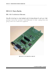

DR-915 OEM DATA RADIO MODULE
___________________________________________________________________________________________
Revision I INTEGRATOR’S GUIDE
17
interface. Applications requiring RS-232 must use an appropriate interface circuit
or a DR-915 RS-232 interface board.
PIN 5 – Transmit Data
This is the data sent by the user device for the radio to transmit. The data
format is a standard asynchronous stream at the user-set baud rate with one
start bit (low) followed by 8 data bits and at least one stop bit (high). This is a
TTL-level interface. Applications requiring RS-232 must use an appropriate
interface circuit or a DR-915 RS-232 interface board.
PIN 6 – Reset
Taking this pin low will reset the radio’s micro controller. For normal operation,
this pin should be left open.
PIN 7 – SPI Clock
This is the SPI clock signal. Data is clocked into and out of the DR-915 on the
rising edge. This pin is also used for updating the code in the radio.
PIN 8 – SPI MISO
This is the SPI data from the radio to the host when in SPI mode. This pin also
indicates a failure to complete an transmission while in Ack-Back™ mode. This
pin is also used for updating the code in the radio.
PIN 9 – SPI MOSI
This is the SPI data to the radio from the host when in SPI mode. This pin also
indicates the radio is attempting a transmission while in Ack-Back™ mode. This
pin is also used for updating the code in the radio.
PIN 10 – VCC
This is power to the radio. It should be 7.5 to 15 vdc.