
Product Manual


INSTALLATION AND MAINTENANCE MANUAL FORM #PM-007 REV C 09/13
Page 6 of 7
For assembly drawings, parts lists, or specific repair instructions, refer to web site at www.coxreels.com or consult factory.
Coxreels, Inc., 5865 S. Ash Ave., Tempe, Arizona, USA, 85283 Tel: 1-800-269-7335
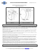
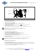
FIG 3.0
SPRING CANISTER REPLACEMENT (AIR SIDE)
• Pull out approximately 3 feet (1m) of hose and latch the reel.
• Remove outlet nozzle, gun or tool and hose stopper.
• Carefully unlatch the reel and firmly hold the drum. Allow the drum to slowly unwind until it stops.
• Remove the retaining ring, spacer and swivel unit.
• Remove the two nuts located on the support post side inside the drum cavity. Do not attempt to remove the spring canister nuts.
• Pull spring canister off drum and axle shaft.
• Reverse above procedure to re-assemble.
• Re-tension the reel by turning the drum three complete turns clockwise (from swivel side) and latch the drum.
• Feed the hose through the hose guide. Fit hose stopper, then unlatch the drum. Hose stopper should sit snugly against the hose guide.
CAUTION: Release line pressure prior to making any repairs or adjustments to the reel.
SPRING CAN REPLACEMENT (ELECTRICAL SIDE)
• Pull out approximately 3 feet (1m) of cable and latch the reel.
• Release all spring tension by removing five wraps of cable from reel.
• Carefully unlatch the reel and firmly hold the drum. Allow the drum to slowly unwind until it stops.
• Remove the input strain relief cap. Remove two acorn nuts to take off cover.
• Refer to figure 3.0 to become familiar with components before performing the following steps.
• Disconnect wires at wire nuts. Remove inlet port from the main axle.
• Remove two coupling nuts located on the electrical mounting plate. Allow the electrical assembly to swing out of the way.
• Remove two spring canister mounting nuts from opposite side of drum assembly.
• Pull spring canister off drum shaft.
• Reverse above procedure to re-assemble.
• Re-tension the reel by turning the drum three complete turns and latching in place. Follow “Spring Tension Adjustment” procedure.
CAUTION: Disconnect from power source prior to making any repairs or adjustments to the reel.
REPLACEMENT/INSTALLATION OF LEAD-IN CABLE
• Remove Input Strain Relief Cap. Remove Cover.
• Disconnect existing Lead-in Cable Wires from Slip Rings and remove Lead-in Cable. Note: Be sure to note which wire goes to which Slip Ring.
• Strip insulation from Cable approximately 2” from Cable end, exposing the individual wires.
• Thread Cable through Strain Relief Cap, Strain Relief, Cover and Inlet Port, respectively. Thread each wire through the holes provided in the Inlet Port.
• Connect wires to Slip Rings using Wire Nuts. (Wire path must begin and end with the same color.)
• Install Cover and secure in place. Replace input strain relief.
Ring Terminal
Electrical Mounting
Plate
Inlet Port
Spring Finger
Wire Nut
Green Ground
Wire