
Product Manual

INSTALLATION AND MAINTENANCE MANUAL FORM #PM-007 REV C 09/13
Page 5 of 7
For assembly drawings, parts lists, or specific repair instructions, refer to web site at www.coxreels.com or consult factory.
Coxreels, Inc., 5865 S. Ash Ave., Tempe, Arizona, USA, 85283 Tel: 1-800-269-7335
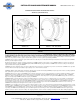
INSTALLATION OF OUTLET HOSE
NOTE: Before proceeding, ensure that you are installing the proper size, length and type of hose that the reel is rated for. Consult factory if unsure of rating.
Damage may occur if wrong hose is installed.
• Securely stabilize the reel.
• Wind the reel drum clockwise (facing the swivel) until the spring is tight.
• Use Extreme Caution! Back off approximately two turns and lock the reel drum to keep from rotating.
• Insert the MALE fitted end of the hose through the roller guide arm and through the cutout in the side of the drum flange.
• The MALE hose fitting should now be on the outside of the drum. Apply thread sealant, connect hose fitting to the swivel joint and secure the hose rigid with the
(two) hose clamps.
• CAREFULLY release the locking ratchet and SLOWLY allow the hose to retract onto the reel.
SPRING TENSION ADJUSTMENT
• Release line pressure prior to making spring adjustments.
• Disconnect inlet hose.
• Pull out approximately 6 feet (2m) of hose and latch the drum.
• Add or subtract one wrap of hose as desired to acquire the proper tension on the reel.
NOTE: Spring tension adjustment is accomplished by adding wraps of hose around the drum (to increase tension) or subtracting wraps of hose (to decrease
tension).
CAUTION: Improper tensioning of spring or adding too many pre-wraps may cause damage to spring mechanism. Only authorized personnel should make
adjustments.
• Unlatch drum and check for proper tension. Connect Inlet hose.
SWIVEL SEAL REPLACEMENT
• Remove inlet hose from swivel.
• Remove swivel from reel by unscrewing swivel from shaft. Disconnect hose from swivel.
• Remove retaining ring on swivel; pull out shaft from body.
• Replace the seals, lubricate and reassemble swivel.
• Fit hose to swivel then fit swivel to reel. Do not over-tighten.
• Reconnect inlet hose and test for leakage.
REPLACEMENT/INSTALLATION OF OUTPUT CABLE
• Disconnect power source.
• Wind the Reel Drum clockwise (facing the cover) until the Spring is tight.
• Use Extreme Caution! Back off approximately two turns and lock the Reel Drum from rotating.
• Remove Input Strain Relief Cap. Remove Cover.
• Disconnect existing Output Cable Wires from Brushes & Ground, remove Cable Clamps/Strain Relief bushing and remove cable from reel.
NOTE: Be sure to note which wire goes to which Brush.
• Insert the bare wire end of the Cable through the Roller Guide Arm and through the cut-out in the side of the Drum Flange.
• The bare wire end should now be on the outside of the Drum. Secure the Cable using the Cable Clamps/Strain
• Relief Bushing allowing approximately 10" of Cable through second Clamp/Bushing.
• Attach Ring Terminal to the Green Wire on the Output Cable and secure to Stud Post. Connect other wires, by color, to their respective Brush. (Wire path
must begin and end with the same color.)
• Install Cover and replace input strain relief cap.
• CAREFULLY release the Locking Ratchet and SLOWLY allow the Cable to retract onto the Reel.
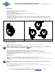
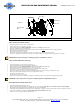
SLIP RING BRUSH REPLACEMENT
• Disconnect power source.
• Remove input strain relief cap. Remove cover. See Figure 3.0.
• Disconnect brush from wire and remove spring finger.
• Reverse above procedure to re-assemble.