
Product Manual

INSTALLATION AND MAINTENANCE MANUAL FORM #PM-007 REV C 09/13
Page 4 of 7
For assembly drawings, parts lists, or specific repair instructions, refer to web site at www.coxreels.com or consult factory.
Coxreels, Inc., 5865 S. Ash Ave., Tempe, Arizona, USA, 85283 Tel: 1-800-269-7335
MOUNTING OF REEL
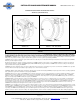
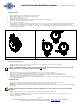
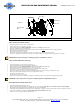
• Reel is supplied with guide arm in standard positions as shown in figure 1.0.
• Guide arm may be adjusted to desired location as shown in figure 2.0.
• Remove swivel on air side of reel.
• Remove retaining clip and spacer from axle.
• Carefully pull out reel drum approximately 1” from center post or just enough to access arm guide bolts.
• Remove bolts and reposition arm guide to desired location.
• Re-assemble reel in reverse order.
• To mount reel to a solid structure you will need four 7/16” or M12 bolts, washers, and nuts. Four masonry bolts may be used depending on mounting application.
Mounting hardware is NOT provided. The mounting base of the reel has two ½” slots and two ½” holes. Mounting patterns will vary depending on model.
• Loosely fit two pieces of mounting hardware to ceiling/floor/or wall so that reel can be slid into position. Fit reel. Install two pieces of hardware in other end of reel.
Securely fasten all bolts and nuts.
Fig 1.0 FIG 2.0
INSTALLATION OF INLET HOSE
• Apply thread sealant to inlet hose and connect to the swivel joint on reel. Note: A swivel type connector is required on supply line.
• DO NOT over tighten and damage swivel or threads.
CAUTION: IT IS IMPORTANT TO USE A “FLEXIBLE” INLET HOSE. DO NOT USE SOLID PIPING OR RESTRAIN INLET HOSE AS TO CAUSE ANY SIDE
FORCE ON SWIVEL JOINT. THE WARRANTY IS VOID IF NOT PROPERLY INSTALLED.
• Flush some product through the system before connecting inlet hose to the source. Connect end to supply source.
• Install inlet hose into swivel assembly by hand tightening, followed by ½ turn with wrench. DO NOT over tighten as it may damage swivel.
• If reel includes hose (Otherwise, See Installation of Hose), flush some product through system before connecting end fitting, nozzle, or tool.
• Apply thread sealant to outlet hose fitting. Connect end, nozzle, or tool as desired.
• If hose stopper adjustment is required to allow easy reach of end fitting or tool. Latch reel at approximate desired location; loosen (two) ball stop bolts. Move ball
stop and tighten bolts. Unlatch reel.
OPERATIONAL CHECK
• Check reel for correct operation by slowly pulling out hose/cable. A clicking noise will be heard after each half revolution of the drum.
• LATCH the reel. Pull out the hose/cable and allow it to slightly retract after the first, second or third “click” is heard.
• UNLATCH the reel. Slowly pull the hose/cable until the clicking noise stops, and then allow the hose/cable to retract. The hose/cable stopper should rest against
the roller guide.
CAUTION: DO NOT ALLOW HOSE/CABLE TO RETRACT WITHOUT RESTRAINING RECOIL SPEED. NEVER LET GO OF THE HOSE/CABLE WHEN
REWINDING.
• Apply line pressure and inspect for leaks. Periodically check hose for improper wear and swivel for possible leaks.
• Reels are shipped with approximately three pre-wraps of tension. This is adequate for most applications. However, if your application requires more or less
tension, see “Spring Tension Adjustment” instructions.
• Lubrication is NOT required.