
Product Manual


INSTALLATION AND MAINTENANCE MANUAL FORM #PM-004 REV E 09/13
Page 4 of 5
For assembly drawings, parts lists, or specific repair instructions, refer to web site at www.coxreels.com or consult factory.
Coxreels, Inc., 5865 S. Ash Ave., Tempe, Arizona, USA, 85283 Tel: 1-800-269-7335
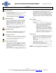
FIGURE 5.0 “EA” MOTOR DIAGRAM (DOUBLE POLE SINGLE THROW) FIGURE 6.0 “EA” MOTOR DIAGRAM (TRIPLE POLE SINGLE THROW)
HOOK-UP AIR MOTOR
CAUTION: DO NOT EXCEED 100 PSI MOTOR INLET PRESSURE.
USE AN FRL OR CONTROL VALVE (IN LINE) TO ADJUST SPEED.
• A suitable sized filter/regulator/lubricator must be installed in the
compressed air line within 3-6 ft. from the motor.
• Use pipes that are the same size as the motor ports for lengths up to
6 ft. from the main line and pipes that are larger for lengths that are
longer than 6 ft. Remove plastic plugs from two ports in motor and
follow steps for muffler or 4-way valve / muffler installation.
• A muffler (provided) must be connected to the outlet port on single
rotation applications.
• When motor is going to be driven in both directions, a 4-way valve
(not included) may be used by being connected to both ports of the
motor. Muffler must then be connected to the air outlet pipe or valve
port.
• Do not use thread tape to seal pipe threads. Use only the correct pipe
sealant on the threads.
• This motor requires LUBRICATION. Use GAST lubricating oil part
number UK5220 or equivalent. Fill reservoir to correct level.
• Apply air pressure, and inspect reel to determine proper operation.
SWIVEL SEAL REPLACEMENT
• Remove inlet hose from swivel.
• Remove swivel from reel by unscrewing swivel from shaft. Disconnect
hose from swivel.
• Remove retaining ring on swivel; pull out shaft from body.
• Replace the seals, lubricate and reassemble swivel.
• Fit hose to swivel then fit swivel to reel. Do not over-tighten.
• Reconnect inlet hose and test for leakage.
NOTE: Swivels designs vary depending on the reel model. Refer to repair
procedure shipped with individual seal replacement kits or consult factory.
CAUTION: Release line pressure prior to making any repairs or
adjustments to the reel.
CHAIN REPLACEMENT (1175-1195 Only)
• Remove motor as instructed. See “Motor Replacement”.
• Remove chain master-link.
• Install new chain. Adjust chain tension and install motor as instructed. See
“Motor Replacement”.
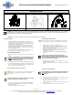
MOTOR REPLACEMENT
CAUTION: Before replacing motor, remove electrical or fluid pressure
from reel.
• Disconnect wiring/fluid line pressure from motor.
• Remove bolts securing motor and/or bracket to reel. See figures 7.0
or 8.0 depending on reel model.
• Install replacement motor. Align gears or chain/sprocket depending
on reel model.
FIGURE 4.0 “E/ED” MOTOR DIAGRAM (SINGLE POLE SINGLE THROW)