
User Manual

FCC ID: QQRBSMR1W60
BDA OPERATION
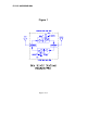
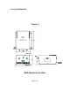
Refer to figure 3 for adjustment access location and label.
ALC (Automatic Level Control)
To minimize intermodulation products, each amplifier in the BDA contains an
ALC feedback loop. The ALC circuit senses the output power and limits it to the
factory preset level of +24 dBm.
ALC function is selected with an on/off toggle switch located on each amplifier
and accessible via the adjustment access panels located on the sides of the BDA
enclosure (Left, or “BASE” side is Downlink, right, or “MOBILE” side is Uplink). A
red indicator lamp located on each amplifier illuminates when output power
exceeds the ALC set point. The indicator is functional regardless of the position
of the ALC switch.
Units are shipped with the ALC switch in the “ON” position.
MGC (Manual Gain Control)
BDA gain can be reduced by approximately 15 dB with screwdriver-adjustable
potentiometers located on each amplifier. The potentiometers accept a 3/32”
slotted screwdriver (provided), and are accessible via the adjustment access
panels located on the sides of the BDA enclosure (Left, or “BASE” side is for
Downlink, right, or “MOBILE” side is for Uplink).
When ALC operation is selected, the MGC serves as the “master”, controlling the
gain, and lowering the effective ALC set point. MGC cannot raise ALC set point
above its factory preset level.
If operation below the 24 dBm ALC set point is desired, BDA gain/output level
can be reduced by turning the MGC potentiometer clockwise until the light goes
off.
Operation of BDASMR1W60 at maximum gain with greater than -25 dBm
average power incident on either BASE or MOBILE port can cause damage
to the BDA.
Page 11 of 13