
User Manual

FCC ID: QQRBSMR1W60
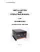
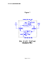
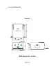
BDA INSTALLATION
DO NOT APPLY A.C. POWER TO THE BDA UNTIL CABLES ARE
CONNECTED TO BOTH PORTS OF THE BDA AND THE
ANTENNAS.
1. Mount the BDA on the wall with the RF connectors pointing DOWN.
Using appropriate screws and anchors, attach the BDA to the wall at the
four mounting holes on the side flanges.
2. Ensure that the isolation between the donor antenna and the service
antenna is at least 12 dB greater than the BDA gain. (Use the higher of the
Uplink and Downlink gains reported on the BDA test data sheet).
3. Connect the cable from the donor antenna to the BDA connector labeled
“BASE” and the cable from the service antennas to the BDA connector
labeled “MOBILE”.
4. Open the adjustment access panels on the sides of the BDA and verify
that both of the ALC switches are in their factory preset “ON” positions.
Close the panels.
5. Connect the AC power cord to the BDA and then to the power source.
Verify that the “Power ON” lamp is illuminated.
Installation of the BDA is now complete. To adjust the gain controls to suit
the specific signal environment, refer to the next section of the manual.
Page 10 of 13