
User Manual

BDA OVERVIEW:
The BDA assembly extends the coverage area of radio communications in buildings
and RF shielded environments.
The unit features low noise figure and wide dynamic range. It is based on a duplexed
path configuration with sharp out of band attenuation allowing improved isolation
between the receiving and transmitting paths.
BDA BLOCK DIAGRAM DESCRIPTION
:
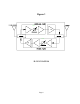
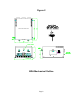
Refer to figure 1 for the following discussion.
The BDA Downlink path receives RF signals from the base station and amplifies and
transmits them to the subscriber. The BDA Uplink path receives RF signals from the
subscriber and amplifies and transmits them to the base station. The Uplink and
Downlink occupy two distinct frequency bands. For example, the PCS A frequency
bands are as follows: 1850-1865 MHz for the Uplink and 1930-1945 MHz for the
Downlink. Two diplexers isolate the paths and route each signal to the proper
amplifying channel.
A selectable Automatic Level Control (ALC) allows for output power limiting. A
variable step attenuator provides 30 dB of attenuation in 2 dB steps. The use of
these controls is covered in the “OPERATION” section, later in this document.
Page 3