
User Manual

BDA OPERATION
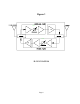
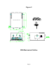
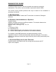
Refer to figure 3 for adjustment access location and label.
Variable Step Attenuator
BDA gain can be reduced by up to 30 dB in 2 dB steps using the variable step
attenuator (Figure 3). Gain adjustment is made with rotary switches accessible via
the access door on the BDA enclosure. Arrows on the shafts of these switches point
to the value of attenuation selected. BDA gain can be determined by subtracting the
attenuation value from the gain reported on the BDA Test Data Sheet for that side of
the unit. The attenuators are labeled for Uplink and Downlink.
ALC (Automatic Level Control)
To minimize intermodulation products, each amplifier in the BDA contains an ALC
feedback loop. The ALC circuit senses the output power and limits it to the factory
preset level of +25 dBm.
ALC function is selected with an on/off toggle switch located on each amplifier and
accessible via the adjustment access panels located on the sides of the BDA
enclosure (Left, or “BASE” side is Downlink, right, or “MOBILE” side is Uplink). A red
indicator lamp located on each amplifier illuminates when output power exceeds the
ALC set point. The indicator is functional regardless of the position of the ALC switch.
Units are shipped with the ALC switch in the “ON” position.
If operation below the 25 dBm ALC set point is desired, BDA gain can be reduced by
adjusting the variable step attenuator until the light goes off.
Operation of BDA-PCS/X-1/1W-XX-A at minimum attenuation with greater than
-35 dBm average power incident for 65dB gain units and -50 dBm average
power incident for 80dB gain units on either BASE or MOBILE port can cause
damage to the BDA.
Page 11