
Installation Manual

2
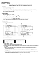
O Output power indicator
Output power indicator shows the power draw from the power inverter by the load. Ideally, the output
power indicator should remain in the green & orange area of the bar chart.
If the output power indicator is up to the red area, the OLP LED will flash and the inverter will shut down.
P Battery voltage indicator
Battery voltage indicator will move up and down as the battery voltage changes. Ideally, the voltage
should remain in the green area of the bar chart. If the voltage goes into the red area at the top and
bottom of the bar chart, inverter may shut down.
Q Other Indicators
z OVP (Over voltage protection indicator)
It indicates that the power inverter shuts down because its input voltage is above limit voltage.
z UVP (Under voltage protection indicator)
The under voltage indicator is to indicate the inverter shut down due to under voltage protection.
z OLP (Overload protection indicator)
The overload indicator is to indicate the inverter shut down due to short circuit or overload protection.
z OTP (Over temperature protection indicator)
The over temp indicator is to indicate the inverter shut down due to over temperature protection.
Once the inverter cools down, the indicator will turn off automatically.
z INV. indicator
The INV. indicator is to indicate the inverter is ready.
z PWR.SAV. Indicator Power saving functions are described below
LED Meaning Inverter Output
Solid Ready ON
Flashing Active OFF
Off Inactive
z GRID indicator
The GRID indicator is to indicate the AC Grid is connected to inverter.
(For SP series: Only functional when connecting SP Series with TR-40)
z CHG indicator
The CHG indicator is to indicate the battery charging status (Only applicable to SL series).
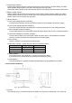
3-2. Rear Panel Introduction
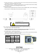
h Aux port
The connector (Fig.3) connected to AUX wire (AWG 14 or 16) must connected with 12V / 0.5A fuse.
Fig.2 Rear Panel Introduction Fig.3 Aux Connector