Costar Video® Web Admin User’s Manual Version 4.12 October 10, 2011 Costar Video Systems, LLC www.costarvideo.com 101 Wrangler, Suite 201 • Coppell, Texas 75019 • Phone: 469-635-6800 • Fax: 469-635-6822 • Toll Free: 1-888-694-STAR (7827) www.costarvideo.
Web Admin User’s Manual Index 1. 2. 3. Admin Menu of Costar Video Servers ........................................................................................... 6 1.1. Entering Admin Menu ................................................................................................... 6 1.2. Admin Menu Structure ................................................................................................. 7 Quick Configuration ...............................................................
Web Admin User’s Manual 5. Device Configuration ................................................................................................................ 28 5.1. 5.1.1. Serial Input Mode ............................................................................................... 28 5.1.2. Serial Output Mode ............................................................................................. 29 5.1.3. Transparent Mode ................................................................
Web Admin User’s Manual 8. 7.7. Clear Recording Configuration .................................................................................... 88 7.8. Delete Recorded Data ................................................................................................ 88 Utilities .................................................................................................................................... 90 8.1. System Log ...................................................................
Web Admin User’s Manual Costar Video® Admin User’s Manual Document Version: 4.12 Revised: October 10, 2011 About This Document This document is prepared for users of Costar Video products supplied by Costar Video Systems, LLC. It is assumed that the users are familiar with network equipment such as LAN, Hub, router, and having basic knowledge of network terminologies.
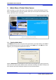
Web Admin User’s Manual 1. Admin Menu of Costar Video Servers After connecting to a Costar Video server on the web browser, you’ll find the web page as shown below. The rightmost item of the menu is Admin, where you can set up the most of features in the Costar Video Server you’re connecting to. 1.1. Entering Admin Menu Click Admin item of the menu, then you’ll see a login window. In the login window, enter root for both ID and password as they are the factory defaults.
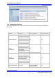
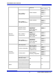
Web Admin User’s Manual 1.2. Admin Menu Structure The following table shows the hierarchy of the Admin menu structure that we’re going to deal with in this manual. Category Main Menu Level 1 Sub-Menu Level 2 Sub-Menu n/a n/a Step 1 Step 2 Step 3 Quick configuration Step 4 Step 5 Step 6 Finish Server Name Setup Date & Time System Configuration Admin.
Web Admin User’s Manual Built-in module 0 (FW-3450/5470) PTZ Mode Built-in module 0 Built-in module 1 Camera & Motion Camera Camera Camera Camera DI/DO DI Status / DO Control Built-in module 1 ( FW-3850/5850/5870) DI/DO DI Status / DO Control Advanced Configuration Recording Configuration n/a Camera Camera Camera Camera Camera & Motion 1 2 3 4 1 2 3 4 n/a Advanced Services (Network cameras) E-mail FTP(Buffered) FTP(Periodic) Sensor Notification Alarm Output Built-in module 0 (FW-3450/5470)
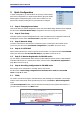
Web Admin User’s Manual 2. Quick Configuration In Quick Configuration, you will be able to set up many of the essential parts of the configuration in a simple manner without going into details. Selecting Quick Configuration gives you the menu as below. You can perform each setup by clicking the one you would like to configure. 2.1. Step 1: Changing Server Name Click Server Name on System Configuration menu, then Server Name Setup windows will be displayed. See the section 3.
Web Admin User’s Manual 10 Costar Video Systems, LLC
Web Admin User’s Manual 3. System Configuration Menu When you click on System Configuration item on Admin Menu, the following sub menu will be displayed. 3.1. Server Name Setup Click Step 1 on Quick Configuration, then the following will be displayed and you will find out the system information such as model number of the Costar Video Server, server name, MAC address (serial number), firmware version, and Webimage version.
Web Admin User’s Manual If you only changed Date and Time setting, simply click Apply button to take it into effect immediately. If you want to retrieve the exact current time from NTP server on the network, click Get NTP Server Time button. Clicking Refresh button will display the date and time retrieved from Costar Video® Server. Then click Apply button to save it.
Web Admin User’s Manual 3.4. Access Control Click Access Control on System Configuration menu. The following windows will be displayed. From the Access Permission window, select either one you would like to use. Click Apply button to save the change. • Full Access: Any user can access the server and use all the features without limit. • Limited Access: Only registered users can access the server and have limited privileges. 3.5.
Web Admin User’s Manual • Selective Access: User is allowed to use only the selected features. With this item selected, user can now configure the details under the menu. Costar Video Server can have multiple VS modules registered in it. When user ticks on any of Enable checkboxes, other fields in that row are enabled to select. • VS Module ID: The registered user can select VS Modules that are available. (VS Module is a network device that has been registered in Costar Video® Server) • Camera No.
Web Admin User’s Manual From the list of the users, select a user to delete. Click Delete button to confirm the deletion. 3.6. IP Devices Registration In this section, you can add NVS (Network Video Server) and NCS (Network Camera Server) to the NVR (Network Video Recorder) as remote server devices. You can delete them from the server as well. After each addition of VS Module ID (IP Devices), make sure to click Apply button to save settings. 3.6.1.
Web Admin User’s Manual Item Description Vendor Vendor’s name of the server Model Number of the channels to be added Name Name of the server IP Address IP Address of the server VS Module ID Applicable to Costar Video only. Enter 0 for other vendor’s models. For FW-3850, FW-5071, FW-5450, FW-5470,FW-5850, or FW-5870, you can enter the value from 0 to 16.
Web Admin User’s Manual After setup is finished, click Save button to add the server. If Delete button is pressed, the added server is removed from the setup and Live Viewer doesn’t provide you the video. Note: After you’re back to the I P Device R egistration menu by clicking Save button, make sure to click Apply button to take the changes into effect. Costar Video Server supports vendors such as Axis, Panasonic, Vivotek and more than 10 others as well as Costar Video products.
Web Admin User’s Manual 4. Network Configuration Configuration the network is dependent on how an IP address is assigned in Ethernet-based environment, which is static IP, dynamic IP (DHCP), or PPPoE. For wireless LAN, additional configuration is necessary to have a connection with wireless AP. In the case of wireless models, users have to choose between wired or wireless connection. In other words, both connections can’t be used at the same time.
Web Admin User’s Manual For static IP, select static IP and input values for IP address, NetMask, Gateway, DNS1, DNS2 and click apply for saving settings. After apply, program will ask closing web brower for updates, which will take 20~30 seconds. If Back button is pushed while configuration, all values will be discarded. If Refresh button is pushed, the program will load previous values. 4.1.2. DHCP Client Configuration For DHCP, DHCP server must exist in the network environment.
Web Admin User’s Manual 4.2.1. ESSID ESSID(or SSID) stands for an dedicated name of AP(Access Point). Whether typing name of AP manually or select from results after scanning nearby AP. To scan nearby AP, click Scan IP, which will pop up a new window. After a few seconds, results will be shown. Click desired AP from list. Note: Access points that are set to hide ESSID information for security won’t be scanned by this method. 4.2.2.
Web Admin User’s Manual For WPASK or WPA2PSK, TKIP and AES can be available and the max length of encryption key is 63 digits of ASCII. 4.3. Network Ports In this configuration, you set up the HTTP port for Costar Video Server to communicate with the Client PC. HTTP Port is the network port that is used when a Client PC connects to the Costar Video Server’s Web page. It can be assigned between 80 and 65535 and the default value is 80.
Web Admin User’s Manual data size transferred from Costar Video products won’t exceed bandwidth limit set by users. If transferred data is exceeded, part of data will be randomly lost If multiple users try to access a FW product which bandwidth control is enabled, users connected to the FW product will share network bandwidth limit. Note: This bandwidth control feature works fairly well in M-JPEG video transmission. But, for MPEG-4 and H.
Web Admin User’s Manual 4.6. Network Status Notify This feature helps to send updated network status information to registered email address if any changes happen. This function will work under DHCP or PPPoE.
Web Admin User’s Manual First, select Enable to use the feature. Then enter the address of the SMTP server which is needed for email service. If your SMTP server requires a user ID and a password for authentication, you will have to get them from ISP or network admin. Enter the ID and password. In Sender field, enter your email address or other meaningful words that will show the message was sent from the Costar Video server as a notification.
Web Admin User’s Manual found from IP-CCTV DNS Setup menu. Enable service and click Apply. If it is configured properly, you can check the result by clicking Confirm button. . Note: Refer to IP-CCTV DNS™ User’s Manual for further details of the configuration. 4.8. Port Forwarding & UPnP UPnP(Universal Plug and Play) is a kind of network protocol to help users to find and configure network products in same local network area.
Web Admin User’s Manual 4.9. RTP/RTSP Setup RTSP (Real-Time Streaming Protocol) is a protocol to transfer video and audio stream over the network. Any application supporting Standard RTSP can be used for Costar Video server. Quick Time Player or VLC program can be used for this, but it may not be supported in the environment within firewall. There are two types of usages, one for Unicast address condition and the other for Multicast address condition.
Web Admin User’s Manual Service RTSP Port Enable: Start RTSP service Disable: Stop RTSP service In normal case, use default port number 554 to connect to RTSP service. If not using port 554, enter the port number you want to use. e.g.) port number 445==> rtsp:// network video server ip address:445/cam0_0 RTP Start Port The starting number of the port for video transfer. Each time video transfer connection is made, the port number also increases. Multicast Address Address for multicast video transfer.
Web Admin User’s Manual 5. Device Configuration You set up the connection between Costar Video Server and the camera in this part of configuration. That includes Video data, external devices, Input / Output, Alarm control, and etc. 5.1. Serial Ports There are two serial ports configurable in the system, COM and AUX. COM port is primarily used for console, and AUX is for PTZ control, but they both can be used for other purposes when necessary. 5.1.1.
Web Admin User’s Manual • Serial Input Model: You can select the sensor’s model number to use for Serial Input. Note: If additional sensors need to be added, it will require installation of the device drivers. The following example is when a speed sensor, AGILIS-HE820-SINGAPORE, is selected.
Web Admin User’s Manual 5.1.3. Transparent Mode When there are two Costar Video Servers present on the network, they can act like a transparent interface between two different UART devices so that the communication between the UART devices can be made transparently without a flaw.
Web Admin User’s Manual After selecting the proper PTZ model from the pull-down list, click Module 0 to activate the camera channel and finish the configuration. Note: Before pFlxwatchhasing receivers or PTZ cameras, please contact Costar Videoor distributor to find out if the product’s protocol is supported by Costar Video server. Note: When a PTZ model is selected from the list, Current Protocol and Current Baud rate will be set to the default values. You can change them if required.
Web Admin User’s Manual Pelco-D : Spectra Dome Pelco-P : Spectra Dome Costar Video: SRX-500/SPT-102 Costar Video: FSD-230/270 Costar Video: FSD-301 ELMO : ELDOME SANTEC : Santec Dome Honeywell : HSDN-230/251(H) Honeywell : HSDN-251(P) SAMSUNG : SCC641/643A SAMSUNG : SCC641/643A(RS422) SAMSUNG : MRX-1000 VICON : V-1311RB VICON : Surveyor-1000/2000 SAMSUNG Techwin : SPD1600 SAMSUNG Techwin : SRX-100B SAMSUNG Techwin : SRX-100R American Dynamics : DELTA DOME KALATEL : CYBER DOME(KTA-xxxx) Panasonic : WV-CS854
Web Admin User’s Manual 5.1.5. PTZ Mode for FW-1160/1161/1177/1178 These Costar Video Servers are Speed Dome models, which are all-in-one type network cameras and have PTZ configuration part. It’s possible to set Preset, Swing, Group, and Tour functionalities in those servers and further detailed parts can be configured by use of OSD. Below is steps for configuration. Click Devices Configuration > Serial Ports > PTZ Mode > Built-in Module 0 > Camera 1.
Web Admin User’s Manual Enter the Preset names as required. You can make up to 32 Preset names. Below is the example of entering 4 different room names. Use the buttons to configure Preset, OSD, Swing, Group, and Tour. (Swing, Group, and Tour are supported in FW-1177PE and FW-1178PE) • Preset & Menu: You can pre-define the spot you want to see. Up to 32 settings can be stored. Click Menu button to configure the camera’s attributes. • Swing: Repeat moving between two positions in certain period.
Web Admin User’s Manual Group Set Click the button and it will display the Group setting window as shown below. Select a group number as you’d like, and click Start Set button. Preset numbers from 1 to 32 will become active for the group. • Speed: How fast it will move between Preset items when Group function is executed. • Time: How long it will stay at the Preset. Each Group can have up to 6 Presets. After Preset is configured, click Save Set button. Group setup window will be displayed.
Web Admin User’s Manual Tour mode. Select a Group number as desired, then click Save Set button to finish setup. The usage of Tour can be controlled at PTZ Control window in Smart Viewer. Swing Set Click the button and it will display the Swing Set window. Use PTZ to direct the camera to put the desired spot on the center of the camera viewing area, then click Set Start Position button. Select the start position and the waiting period, then click Time button.
Web Admin User’s Manual Privacy zone is marked with a rectangular shape. When you click New button, red-colored box will pop up and users can change its size and location. After that, click Apply button which will make box to green-color and finish the configuration.
Web Admin User’s Manual Users can define the Privacy zone as many as 8 parts of the screen. If you add more than 8, an error message will pop up on the screen. To delete a privacy zone, click the zone and click Delete button followed by Apply button.
Web Admin User’s Manual 5.3. Camera & Motion This menu is used to set up the selection of video format, data added to video data, encoding speed, audio control, image resolution, video quality, motion detection, and etc. Click Camera & Motion on Device Configuration menu. The configuration menu will be displayed, and it may be different between Costar Video models. • Watermark: The technique that imposes a particular pattern or code into images.
Web Admin User’s Manual • MPEG-4: In this format, each frame data is related to other nearby frames. For this reason, it provides much higher compression ratio than M-JPEG and is adequate for video transfer. However, if network condition is not very good and having dropped frames in video data, the video quality can be relatively low. With Costar Video server, you can set the number of P-frames in the video which is independent still images between I-frames.
Web Admin User’s Manual • Light Frequency: Used for Flickering Reduction. Select the electric power frequency used in the region, either 50 or 60Hz. Note: Light Frequency param eter is supported only in FW1170. • Frame Rate: For Primary Stream, this is the number of frames compressed in every second. You can control the network traffic with this parameter. For Secondary Stream, it can be set to manner of 1/2, 1/4, 1/8... of the primary stream.
Web Admin User’s Manual Image Quality Setup Rate Control Mode: VBR (Variable Bit Rate) Video frames are encoded with selected image quality and GOP. Encoded frames have different data size from each other. MPEG-4 / H.264 Rate Control Mode: CBR (Constant Bit Rate) Video frames are encoded with selected image quality and GOP. Encoded frames have the same data size as other frames. Due to the constant bit rate, it has better stable transmission performance.
Web Admin User’s Manual • Contrast: Select the contrast of image between 0 and 30. • Sharpness: select the sharpness of image between 0 and 5. • Day & Night Control: If used, the image will be in Color mode during daytime and Black& White mode during night time.
Web Admin User’s Manual Motion Detection • Motion Detection: If enabled, Motion Detection feature is activated and user can configure the areas where motion detection function will work. (this is only available in Primary Stream) • Motion Sensitivity: Set the sensitivity of motion defined in Motion Detection Area. Select between -100 and 100. 100 is the most sensitive. After all the setting is done, click Apply button to save it. If Default button is clicked, all the fields return back to original value.
Web Admin User’s Manual • Default Video Format (FW-3170 only): Select the video transmission format of the camera attached to Costar Video Server. Select one from NTSC or PAL. • Video with UART sensor Data: If Enabled, video data will contain UART sensor data from COM port. • Video with user defined message: If Enabled, video data will contain the user-defined data. (Reserved Field) • Video with PPP status: If Enabled, video data will contain PPP connection status.
Web Admin User’s Manual Rate Control Mode: VBR (Variable Bit Rate) Video frames are encoded with selected image quality and GOP. Encoded frames have different data size from each other. MPEG-4 / H.264 Rate Control Mode: CBR (Constant Bit Rate) Video frames are encoded with selected image quality and GOP. Encoded frames have the same data size as other frames. Due to the constant bit rate, it has better stable transmission performance. M-JPEG Low Compression GOP Structure: Distance between IFrames.
Web Admin User’s Manual Image Quality Setup Rate Control Mode: VBR (Variable Bit Rate) Video frames are encoded with selected image quality and GOP. Encoded frames have different data size from each other. H.264 Rate Control Mode: CBR (Constant Bit Rate) Video frames are encoded with selected image quality and GOP. Encoded frames have the same data size as other frames. Due to the constant bit rate, it has better stable transmission performance.
Web Admin User’s Manual • Motion Sensitivity: This value sets how sensitively the motion detection works for the motion detection functionality. It can be between –100 and 100 while 100 is the most sensitive. • Motion Detection: This decided whether the Motion Detection is to be used. If Enable is selected, you can set which part of the camera image the Motion Detection does functioning. (Primary Stream only) After configuration is finished, click Apply button to save the setting.
Web Admin User’s Manual (Reserved Field) • Video with PPP status: If Enabled, video data will contain PPP connection status. • Video with camera name: If Enabled, video data will contain the camera name. • Video with server name: If Enabled, video data will contain the server name you defined. • Video with IP address: If Enabled, video data will contain the IP address of the video server. • Time Stamp: If Enabled, encoded video image will have the time display on it.
Web Admin User’s Manual • Camera Name: Enter the name of the channel in up to 21 alphanumeric or up to 10 Unicode characters. • Audio: Select if Audio function is to be used (applies to Primary Stream only) Costar Video Server provides 2-way audio streaming by combining microphone input with video data. Users can listen to the streamed audio on PC speakers. • Video Input: Select to see camera’s connection status.
Web Admin User’s Manual Image Quality Setup Rate Control Mode: VBR (Variable Bit Rate) Video frames are encoded with selected image quality and GOP. Encoded frames have different data size from each other. MPEG-4 M-JPEG Rate Control Mode: CBR (Constant Bit Rate) Video frames are encoded with selected image quality and GOP. Encoded frames have the same data size as other frames. Due to the constant bit rate, it has better stable transmission performance. GOP Structure: Distance between IFrames.
Web Admin User’s Manual Configure the video data format and other information to be contained in it. • Default Video Format: Video transmitting format of the camera attached to Costar Video Server. Select one from NTSC or PAL. • Video with UART sensor Data: If Enabled, video data will contain UART sensor data from COM port. • Video with user defined message: If Enabled, video data will contain the user-defined data.
Web Admin User’s Manual Click Apply button to save the changes. If required, click Built-in Module 1 on Device Configuration menu to set up the other channel as well. Camera Configuration FW-3850 and FW-5850 have two modules, 8 channels respectively. Each channel represent the camera attached to FW-3850 or FW-5850. On the lower part of Module 0 > Camera & Motion Configuration menu, select a channel you want to configure. Enter the detailed parameters of the camera selected here.
Web Admin User’s Manual • Camera Number: The number of the channel in use. Not changeable. (1 to 4) • Camera Name: Enter the name of the channel in up to 21 alphanumeric or up to 10 Unicode characters. • Audio: Select if Audio function is to be used (applies to Primary Stream only). Costar Video Server provides 2-way audio streaming by combining microphone input with video data. Users can listen to the streamed audio on PC speakers. • Video Input: Select to see camera’s connection status.
Web Admin User’s Manual In Image quality level setup, selecting the left results in higher image quality, but requires higher network bandwidth. Selecting the right requires lower network bandwidth, but gives degraded image quality. • Hue: Set the color of image between -100 and 100. • Saturation: Set the intensity of the image between -100 and 100. • Contrast: Set the contrast of the image between -100 and 100. • Brightness: Set the brightness of the image between -100 and 100.
Web Admin User’s Manual Camera Configuration Each camera’s parameters can be defined in this section. Select a channel that you’d like to configure. Set the information of the camera. • Camera Name: Enter the name of the channel in up to 21 alphanumeric or up to 10 Unicode characters. • Image Size: Select the resolution of each channel’s video data. This attribute applies to all the channels. (You may set the Image Size to what you did in IP Devices Registration.
Web Admin User’s Manual SPECIAL (* Refer to the table below) - EXIT Exit from Menu Mode and save settings. Special Menu Function Description CAMERA ID (Name of the camera) Use up to 15 Alphanumeric and space COLOR AUTO / ON AUTO: Automatic switch of Day & Night Mode (Day-time: Color Mode; Night-time: B/W mode) ON: Operate in COLOR mode always. SYNC INT / LL LL: Adjustable between 0 - 359º Trigger Signal: Auto Sensing. Motion Detection OFF / ON ON: Define 4 adjustable positions and sizes.
Web Admin User’s Manual DI/DO functionality can be set to either Normal Open or Normal Closed type as follows. • Normal Open Type: Normal is OPEN, and goes CLOSED when triggered by an event. • Normal Close Type: Normal is CLOSED, and goes OPEN when triggered by an event. Note: Make sure the type of the sensor and use it correctly to the type. If a Sensor Input is not used, it must be set to Normal Open Type to avoid a false input. 5.4.1.
Web Admin User’s Manual 5.4.2. DI/DO for FW-3850/5850/5870 There are 8 serial Input ports and 8 output ports in FW-3850 and FW-5850 models. A good example of the Input and Output usage is, an external sensor can be connected to the Input port, and a warning light is triggered by the Output port. DI/DO Setup Each Input and Output port can be assigned unique name respectively, so that you can easily distinguish every Input and Output ports from others by those names.
Web Admin User’s Manual DI/DO Control FW-3850 and FW-5850 have 8 output ports and they act like a push button. When you click On button, it is essentially like the push button is pressed. When you click Off button, it is like the push button is not pressed. FW-3850 and FW-5850 have 2 built-in Module respectively, and each Built-in Module has 4 Alarm Outputs. The status of Sensor Input can be monitored through DI. When the checkbox is marked, that means the Alarm is activated.
Web Admin User’s Manual 5.4.4. DI/DO for FW-5071 DI/DO Setup You can define Sensor Input Name and Alarm Output Name as you want, which should be up to 31 alphanumeric or up to 15 Unicode characters. After entering the names of Input and Output, click Apply button. (* In this model, it is not allowed to select the type of Sensor Input / Alarm Output) DI/DO Control These two Costar Video models have n Alarm output port and they act like a push button.
Web Admin User’s Manual 6. Advanced Configuration Costar Video can be configured to start and stop certain pre-defined services by scheduling, event, or conditions. It also has ISENS feature, which is a way of integrating Costar Video with CMS software. You can set up the advanced services in Advanced Configuration menu. There are two types of advanced service, one is Buffered Service and the other is Periodic Service.
Web Admin User’s Manual 6.1. Advanced Services Pre-Alarm buffer size and buffering speed can be defined here. • Pre-Alarm Buffer Size: You can set the buffer size which will store the images before event. The unit is in frame, and each channel can be set with different values. The total number of frames for Pre-Alarm Buffer and Post-Alarm Buffer is limited to 10 frames. • Pre-Alarm Speed: You can set the buffering speed. If it’s set to Fastest, the server will store images as fast as it can.
Web Admin User’s Manual • Alarm Output: Set up Alarm Output (DO Control) configuration 6.1.1. E-mail Service Configuration Email configuration is set up here for Alarm in case any event occurs. Item Description Camera 1~2 (max 4) Select a channel to be configured for email notification Service Select Enable in order to use this service SMTP server address Enter SMTP server’s address for sending email.
Web Admin User’s Manual For each channel, the following items can be configured for email service: Condition, Post-Alarm Buffer Size, and Post-Alarm speed. The content of text message and display style of DI value can be configured as well. Item Description Condition 1 ~ Condition 3 Select a condition for Email service to be activated. Pre-Alarm Buffer Size The Buffer size assigned for Pre-Alarm. Check Video buffer Click this link to go to Advanced Services for buffer setup.
Web Admin User’s Manual If you click on a Condition link, the Advanced Service windows is displayed as shown below. Alarm Service is activated only when the conditions in Advanced Services are met. Item Description Service This shows what service this condition is for. Module ID Module ID for current setup Camera ID Channel ID for current setup Enable / Disable Select Enable to use Condition, otherwise select Disable. Always This Condition applies all the time.
Web Admin User’s Manual 6.1.2. FTP (Buffered) Service Configuration Item Description Camera 1 - Camera 4 Select which channel to set up for FTP (Buffered). Service Select Enable to use the FTP (Buffered) service. Otherwise select Disable. Server Address FTP Server Address. Base Directory Name The directory in FTP server where the data will be uploaded. (You should make the directory in the FTP server before using the service.
Web Admin User’s Manual Day If Directory Name is checked, new directory name is created with day. If File Name is checked, new file name is created with day. Hour If Directory Name is checked, new directory name is created with hour. If File Name is checked, new file name is created with hour. Minute If checked, new file name is created with minute. Sec If checked, new file name is created with second. Sequence If checked, new files are created starting from 0, with increment of 1.
Web Admin User’s Manual 6.1.3. FTP (Periodic) Service Configuration Item Description Camera 1 - Camera 4 Select which channel to set up for FTP (Periodic) service Service Select Enable to use the FTP (Periodic) service. Otherwise select Disable. Server Address FTP Server Address. Base Directory Name The directory in FTP server where the data will be uploaded. (You should make the directory in the FTP server before using the service.
Web Admin User’s Manual If Directory Name is checked, new directory name is created with weekday. If File Name is checked, new file name is created with weekday. If Directory Name is checked, new directory name is created with month. If File Name is checked, new file name is created with month. If Directory Name is checked, new directory name is created with day. If File Name is checked, new file name is created with day. If Directory Name is checked, new directory name is created with hour.
Web Admin User’s Manual 6.1.4. Sensor Notification Service Configuration Item Description Input 1 - Input 4 Select which input to set up for Sensor Notification Service Service Select Enable to use Sensor Notification. Otherwise select Disable. Service Mode Select network mode for CGI. Select one among HTTP, TCP, or UDP. Main IP address Enter IP address to use in CGI or other functions Aux1 ~ Aux 3 IP address Enter 3 more addresses to use in CGI or other functions if needed.
Web Admin User’s Manual 6.1.5. Sensor Notification Service Configuration for Each Input Item Description CGI Name or Alarm Port Message Enter the contents of CGI when it is used. Click Save button to save the change. Clicking Back button will cancel the change and go back to previous page. 6.1.6. Alarm Output Service Configuration Category Contents Output 1 – Output 4 Select the output port to configure for Alarm Output Service. Service Select Enable to use the service, otherwise select Disable.
Web Admin User’s Manual 6.1.7. Alarm Output Service Configuration for each Output Item Description Condition 1 - Condition 3 Select a condition to configure Alarm Output Service. Up to 3 conditions can be set respectively. Alarm Output Duration Select how long the Alarm Output signal is maintained. Unit is in second.
Web Admin User’s Manual 7. Recording Configuration for FW-5071/5450/5850/5870 & FW-1170/1173/1175/1176 with microSD Slot It is possible to record and search the video data sent from camera if the Costar Video Server is equipped with a hard disk drive. Recording configuration is available only when a hard drive is up and running in the server. You can format the hard drive, check the information of the drive, and set the recording conditions of motion detection and event.
Web Admin User’s Manual The list of hard drives will be displayed with the format status. Click on the one you’d like to format. If you put check mark on Check Bad Block option, it’ll take much longer time to complete the formatting process. In case of installing a new hard drive, it’s not necessary to use that option. Click Partition and Format button, then a confirmation window will be displayed. Click OK button to proceed formatting, otherwise click Cancel button.
Web Admin User’s Manual Now you will see the HDD Status & Format window, and the status of 1st HDD has been changed to Formatted. If there’re more HDD’s newly installed, go ahead with formatting them. After completing all the hard drive’s formatting, click Reboot button. Reboot process will take about 30 seconds. Then with your PC’s web browser, open the Admin Page of the Costar Video Server, and check HDD Information on Recording Configuration menu.
Web Admin User’s Manual 7.2. microSD Configuration If a microSD card (SD card) is not present in the slot already, turn off the Costar Video network camera before inserting a SD card. Make sure to turn the power on after inserting the SD card. Open a web browser, type in the IP address of the Costar Video network camera. Log in as admin, and run Recording Configuration. Note: Be sure to turn off the device before installing a SD card. Otherwise, the SD card may become defective.
Web Admin User’s Manual Now you will see the list of SD cards available and whether they are formatted or not. To perform formatting the unformatted one, click the SD card. Then the following window will be displayed. Click the Partition and Format button, then a pop-up window will be shown to confirm the formatting. Click the OK button to proceed, or click the Cancel button to abort the formatting.
Web Admin User’s Manual Note: If the program is terminated during the format process, the SD card may be damaged. To avoid this problem, make sure to close the program in the right manner and check the SD card. After formatting is finished, the following window will appear informing it. Click the OK button. On SD Status & Format window, you will be able to see that the 1ST SD is shown formatted. After formatting SD card is finished, click the Reboot button to restart the system.
Web Admin User’s Manual can be also recorded in your device. You can find out the list of servers with recording capability by clicking Recording Configuration. For example, you will see 12 channels from the list of VS Module ID (IP Devices) after adding two FW-3450 devices in IP Devices Registration of FW-5450. That means, FW-5450 can record the video sent from other remote cameras, as well as the four local cameras attached.
Web Admin User’s Manual Item Description Condition 1~4 Set the conditions for recording Graphs for Time, Day of week, Alarm, Motion, Camera Connection Graphic displays of conditions for recording Recording Service Click Enable to record the video. Click Disable otherwise. Server Module ID Camera Number Server ID number of the added VS Module ID (IP Devices). Camera number to select. The name of the camera selected. Use up to 31 Camera Name alphanumeric or 15 Unicode characters.
Web Admin User’s Manual Category Select Mode Schedule Item Always Schedule Only Event Only Schedule and Event Week Time Date Alarm Sensor Event Motion Detection Description Recording is enabled all the time. Recording is done by configured schedule. Recording is controlled by configured event. Recording is controlled by both schedule and event. Set day of week Set time Set date Each of 1, 2, 3, 4 refers to the sensor number, and checked when Event-Driven Recording is selected.
Web Admin User’s Manual Below is an example of configuring the recording condition, which means “Video is recorded if Alarm is activated or Motion is detected, on Saturday and Sunday every week.” If time condition is not specified, it is taken as setting 24 hours. If date is not specified, it is taken as setting all the months and weeks. Click the Back button if you want to return to previous page without saving. Click the Save button to save the change and return to previous page.
Web Admin User’s Manual Example 1) Recording Condition: Always, Schedule • Pre-Recording Speed: 1 fps • Pre-Alarm Count: 5 • Post-Recording Speed: 10 fps • Post-Alarm Count: • Since the recording condition is Always and Schedule, Pre-Recording Speed is in effect. So the recording speed is 1 fps. Other values don’t affect the recording.
Web Admin User’s Manual Now you will notice that the Recording Configuration is made. If the video is already being recorded, the status will display Recording. You need to click the Apply button in this case. If recording conditions are configured properly and video is not being recorded at the moment, you need to click the Record button to start recording. Once recording has been started, the Status field will change to Recording.
Web Admin User’s Manual Note: Record button will become Stop button after pressing. If you want stop recording, click the Stop button again. 7.4. View Recording Profile When it’s needed to check recording configurations which have been made to each camera, it may take quite some time to go through the menu tree. In this case, you can get the overview of the recording configuration by clicking View Recording Profile on the menu. To view the recording profile, click Recording Profile.
Web Admin User’s Manual deleted first to make space for new video. If you want the Costar Video Server to stop recording and let you to replace the HDD, click Pause at full and then select Pause at Full. • Circulation: The base file size for video is 630 Mbytes in HDD. So every time the HDD is out of space, it will delete the oldest 630 Mbytes file to make space. • Pause at full: When the HDD is out of space, it will stop recording and display STOP status.
Web Admin User’s Manual SMTP Server Authentication Login User ID Password Sender 1st Recipient 2nd Recipient 3rd Recipient User Defined Message 7.7. IP address of the server for email service. Select Enable if the SMTP server requires user authentication. User ID for authentication login Password for the User ID Email address of sender Email addresses of the recipients (up to 3 persons). Contents of the message to add in the notification.
Web Admin User’s Manual 89 Costar Video Systems, LLC
8. Utilities In Utilities part of the Admin menu, you can view the system log file, save the changed value during the configuration, reboot, restore the factory default condition, and update the system. 8.1. System Log System log file provides you the information about when and who access the contents of Costar Video Server such as HTTP file or CGI programs. In each line, log data consists of date, time, category, soFlxwatche IP address, user ID logged in. Day of Week 8.2.
Costar Video Admin User’s Manual Configuration on Utilities menu. The confirmation screen will be displayed as shown below. Click Save Configuration button to finalize the action, otherwise click Back button to cancel it. In some Costar Video models which automatically save the configured contents, Save Configuration button will not be displayed. 8.3. Reboot It is recommended to reboot the system after making changes and saving the configuration. To reboot, click Reboot on Utilities menu.
Costar Video Admin User’s Manual 8.5. System Update Costar Video Server’s system program and data are stored in Flash memory, and it consists of Kernel Image, RAM Disk Image, System Image, and Web Image. In order to update the system of the server, you should have proper image files ready in your PC. Click System Update on Utilities menu, then the following window will be displayed. From the Start buttons displayed, choose the one that meets your needs.
Costar Video Admin User’s Manual 1.1.1. All (Kernel, RAM disk, System, Web) Update Click the Start button next to All (Firmware, RAM disk, System, Web) Update item on the menu, and a confirmation window will appear. Click OK button to proceed the update, otherwise click Cancel. Note: If your web browser’s pop-up blocker is enabled, your PC many not display the confirmation window above. In that case, the pop-up blocking feature of the web browser should be disabled for system update to be completed.
Costar Video Admin User’s Manual The next window is for locating the RAM Disk Update file. Go through the same steps as in Firmware Update, and do the same in update process for System and Web Update files. After all the update processes pare finished, the window for Factory Default is displayed. If there was no problem in the entire update processes and you want to continue, click Next button.
Costar Video Admin User’s Manual 1.1.3. Web Only Update Click the Start button next to Web Only Update item on the menu, and a confirmation window will appear. Click OK button to proceed the update, otherwise click Cancel. The rest of the process is the same as in All Update part. After update is done, click Reboot to start the system over. 1.1.4.
Costar Video Admin User’s Manual Now the update process is finished and the window for rebooting will be displayed. Click Reboot button to start the server over. 1.1.5. Sensor Device Driver Update When adding a new Sensor device that doesn’t have a proper driver found in Costar Video Server, it is required to install a driver for it. The name of the file used in update process is SensorModel.bin.
Costar Video Admin User’s Manual Now you can check the file name and the size in the new window. If you want to go back to the previous stage, click Previous button. Click Next button to update the System Image right away and proceed to next stage. If you want to stop the update process, click Cancel button. Now the window to locate the Config Image file is displayed. Select a file after clicking Browse button. Click Next button to move to the next stage.
Costar Video Admin User’s Manual If you click Edit button, now you can edit the Config file after clicking Edit button which is found on the right of the file name. Click Save button to save the Config file. Click Close button to close the editing window. If you click Next button, a window for rebooting is displayed. Click Reboot button, and the system will start over.