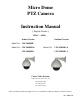
Micro Dome PTZ Camera Instruction Manual English Version 24VAC ~ 60 Hz Indoor Version Outdoor Version Model No: CDC2040MIL Model No: CDC2040MI & Model No: CDC2040MI-1 CDC2040MO & CDC2040MO-1 Costar Video Systems 2720 Commodore Drive, Suite 150 Carrolton TX 75007 Tel: 972-446-8844 Fax: 972-446-8866 Please read this manual thoroughly before use or installation and keep it handy for future reference. Rev.
THIS PAGE IS INTENTIONALLY LEFT BLANK 2
WARNINGS AND CAUTIONS WARNING TO REDUCE THE RISK OF FIRE OR ELECTRIC SHOCK, DO NOT EXPOSE THIS PRODUCT TO RAIN OR MOISTURE. DO NOT INSERT ANY METALLIC OBJECTS THROUGH VENTILATION GRILLS OR OPENINGS ON THE EQUIPMENT.
FCC COMPLIANCE STATEMENT FCC INFORMATION: THIS EQUIPMENT HAS BEEN TESTED AND FOUND TO COMPLY WITH THE LIMITS OF A CLASS A DIGITAL DEVICE, PURSUANT TO PART 15 OF THE FCC RULES. THESE LIMITS ARE DESIGNED TO PROVIDE REASONABLE PROTECTION AGAINST HARMFUL INTERFERENCE WHEN THE EQUIPMENT IS OPERATED IN A COMMERCIAL ENVIRONMENT.
IMPORTANT SAFEGUARDS 1. Read these instructions before attempting installation or operation of dome device. 2. Keep these instructions for future reference. 3. Heed all warnings and adhere to electrical specifications. 4. Follow all instructions. 5. Clean only with non abrasive dry cotton cloth, lint free and approved acrylic cleaners. 6. Should the lens of the camera become dirty, use special lens cleaning cloth and solution. 7. Do not block any ventilation openings. 8.
1 Chapter 1 – Introduction Table of Contents 1.1 Performance Characteristics .......................................................................................................................... 7 1.2 Model Numbers ........................................................................................................................................... 8 1.3 Features and Functions ........................................................................................................................
1. Introduction The CDC2040 xxx Micro series Low to High Speed domes and a series of compatible keyboard controllers make up the building blocks for any size video surveillance system. Using multiple keyboard controllers and multiple high speed dome camera units, one can monitor a variety of environments from small to very large. Extensive and flexible architecture facilitates remote control functions for a variety of external switching devices such as multiplexers and DVRs. 1.
1.2 Model Numbers Model No: CDC2040MIL Model No: CDC2040MI-1 Model No: CDC2040MI Model No: CDC2040MO-1 Model No: CDC2040MO Micro Dome Indoor Low Speed Nylon Housing without OSD Micro Dome Indoor High Speed Aluminum Housing without OSD Micro Dome Indoor High Speed Aluminum Housing with OSD Micro Dome Outdoor High Speed Aluminum Housing without OSD Micro Dome Outdoor High Speed Aluminum Housing with OSD 1.3 Features and Functions • Multi-language on screen menu for operation and function settings.
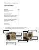
2.0 Installation & Configuration 2.1 Package Contents The dome carton contains the following: Description Qty High Speed Dome mechanism 1 Camera Module 1 Clear Acrylic dome cover 1 Camera shroud (black) 1 Plastic bag W/ Screws (2xM4*10, 2xM4*3) 1 (2xM4*6, 4xM2*4) + Mini Screwdriver O-ring + Adapter for wall or ceiling bracket 6 conductor Control/Power/Video harness 1 24VAC transformer 1500 mA 1 Wall bracket 1 Ceiling bracket 4” 1 Instruction manual 1 Figure 1.
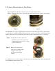
2.2 Camera Shroud removal / installation. Figure 10. Illustrates the camera shroud in position over the camera module Figure 11. Illustrates the location of the tab for the camera shroud in close position (twist On/Off) Fig. 10 Fig. 11 The CDC2040 series dome is equipped with a quick release camera liner supported by 3 tabs attached to a ring affixed to the PTZ mechanism.
2.3 Communication Settings 2.3.1 Dip Switch Location. Before installation and use, the unique address for each dome and the communication protocol including transmission speed (baud rate) should be set to correspond with the chosen control system. In order to set the corresponding dip-switches remove the camera liner as previously illustrated and locate the two Dip-Switch rows (8 & 4) behind the camera module on the main PCB as illustrated. 2.3.
2.3.3 Address setting of each dome. To prevent damage, each dome must have a unique address (ID). On/off switch and matching numbers On/Off switch Example: The sum of switch numbers in the ON position is the address of the dome device. (Binary Method) Setting address for dome device (this figure shows the address of dome device No 1). 128 64 32 16 1 2 4 8 Dome device range: 1~255. Calculation example of dome device address: 2 16 4 2+4+16=22 the dome address is: 22 2.3.
2.4 Wall bracket installation. Step 1: Feed the supplied wiring harness through the channel inside the wall bracket as illustrated in Fig. 13. Verify that the 6 pin connector is remaining outside the opening of the bracket as illustrated in Fig. 14. Fig. 13 Fig. 14 Step 2: Affix the wall bracket to the wall as illustrated in Figure 15 verifying that the surface you are attaching to can support the weight of the dome using either expanding anchors or butterfly fasteners. Fig. 15 Fig.
Note: It is important that you set the dip switch settings for the dome address, communication parameters and protocol BEFORE you install the dome in its physical location of operation. 2.5 Attaching the dome to the bracket Step 1: Locate the small plastic bag containing the O-ring, adapter, screws, and small screwdriver as illustrated. Step 2: Install the O-ring onto the wall bracket as illustrated. Step 3: Install the adapter onto the top of the dome as illustrated.
2.6 Installation of the acrylic dome cover NOTE: The dome is shipped with a protective clear film around the clear bubble. This film should remain in place until you finished with the installation protecting the dome from scratches. The dome cover has two parts, a metal aluminum ring and a clear acrylic dome. The metal ring has male fine threads that will allow it to mate with the aluminum cover of the dome mechanism.
2.7 Wiring Specifications The wiring Harness has a label affixed indicating the Power, Video and Communication conductors. Do not remove this label as it may be a useful future reference. Figure 20 is the illustration of the wiring diagram for the electrical connections to the dome unit. 24V power supply Connect to control keyboard Fig. 20 Note: Observe the Polarity of the RS485 Communications (marked and relevant) for proper communication and operation.
Chapter 3: Wiring and Setup 3.1 Basic Configuration The illustration below provides the basic electrical wiring configuration for connecting and testing a single dome to a test monitor and a joystick / keyboard controller. When installing the product for the first times please read the installation instructions carefully and become familiar with the electrical connections and setup options. Incorrect wiring may result to permanent damage of the equipment.
3.2 Connecting Multiple Domes When connecting multiple domes together, the user has the option to connect video and control terminals to a video matrix switcher or a DVR multiplexer creating an integrated system. AC24V: Power supply Primary 110V/60HZ input to AC 24V output. RS-485 Bus: Control signal output from joystick controller, connected in a bus configuration to the RS485 communication terminals of the control cable for each dome.
4. Quick Start Operation Guide CAUTION: Do not turn the power ON until you have finished all connections and communication settings). 4.1 Connect the power to the dome. As soon as the power is turned ON, the dome initiates a self test which includes a rotation of the dome on both axis and the camera will display a brief menu followed by a live image on the monitor.
4.5 Direct Input Commands for Dome Operation The following preset position addresses are reference to the direct memory location of the dome controller. They do not correspond to memory preset positions in the keyboard controller or software applications that support PTZ preset functions. Please consult the manual of the chosen keyboard controller for correct operation. Dome preset memory locations: No. 1 50, 64 ~77 and 102~165 total 128 preset positions Special Function memory preset location: No.
Setting the Home position: This means the time duration before the dome positions itself to Preset No.1 during a period of inactivity.
4.7 CAMERA OSD MENU The following section is specific to the Camera module installed in the CDC2040MIL Dome. The available options (menus and sub menus) can be accessed directly from the keyboard by entering 57+SHOT+ACK or 57 + PRESET depending the model and type of the selected keyboard controller.
5. Program and Operation NOTE: The following instructions apply only to the following models with OSD (On Screen Display) functions: CDC2040MI and CDC2040MO 5.1 Main menu The following commands are references to the keyboard controlling the dome. Depending the make and model of the controller these commands may vary slightly. For reference purposes the following key labels / acronyms are used: SHOT = PRESET or PRST - ACK = ENTER - OPEN =Iris open - CLOSE = Iris Close 1.
5.2. A detailed tree of the OSD menu and sub menus is illustrated below. 5.2.1 5.2.2 5.2.3 5.2.4 5.2.5 5.2.6 Note: Due to space limitations not all screen shots are displayed on this page. Additional information is displayed in subsequent chapters in this instruction manual.
5.2.1. Language Selection The default is English; Depending on the country of sale different options are available. Moving the joystick right allows the user to select different language menus. As an example the screens below illustrate the transition from English menu to Spanish. 5.2.2. Display Options 1. Preset position setup options menu 2. Sector setup options menu 3. On Screen display of X,Y camera position 4.
5.2.2.1.2 Set Preshot Move the Dome camera to the desired position on all 3 axis (P,T,Z) and then press IRIS CLOSE button to confirm the preset position location and return to the previous menu. The menu will display “Stored” confirming that the position has been set in the dome memory. If you do not see the confirmation repeat the process as there may be a latency of communications depending the wiring method and the number of devices connected on the RS485 Loop. 5.2.2.1.
5.2.2.1.6 Name Display Move the joystick Left or Right to select ON or OFF Based on your selection the name you have entered for this preset position will be displayed (or not) on the screen when the PTZ positions itself to this preset position. Press IRIS CLOSE button to exit and return to the previous menu level. 5.2.2.2 Sector Setup On the Display Option menu move the joystick to select the Sector Setup Menu.
Move the joystick Left or Right to select desired character (0~~9 or A~~Z). Press IRIS OPEN button to confirm selection and move to the next character of choice. Press IRIS CLOSE button to exit or return to the previous menu level when programming is done. Press IRIS OPEN button to confirm Press IRIS CLOSE button to exit and return to the previous menu level. 5.2.2.2.3 Pan Start POSITION Move the joystick up or down to the desired selection.
5.2.2.2.5 Tilt Start POSITION Move the joystick up or down to the desired selection. Move the joystick right to make your selection and display the on screen coordinates. Using the joystick move the pan & tilt to the desired Tilt Start coordinates for the selected sector. Press IRIS CLOSE button to set the Tilt Start position coordinates and return to the previous menu level. 5.2.2.2.6 Tilt End POSITION Move the joystick up or down to the desired selection.
5.2.2.3 Coordinates Move the joystick up or down to the desired selection. Move the joystick Left or Right to select ON or OFF Based on your selection the On-Screen X-Y position coordinates will be displayed at the bottom of your screen. Press IRIS CLOSE button to exit and return to the previous menu level. 5.2.2.4 Start Up Message Move the joystick up or down to the desired selection.
5.2.3. Control Options Move the joystick up or down to the desired selection. Move the joystick right to make your selection and display the Control Options sub-menu or Press IRIS CLOSE button to return to previous menu 5.2.3.1 Set Pan & Tilt Move the joystick up or down to the desired selection. Move the joystick Left or Right to make selection. Different options are possible based on the function you selected including sub- menus with additional options.
5.2.3.1.4 Tilt Reverse Move the joystick up or down to the desired selection. Move the joystick Left or Right to choose ON or OFF This allows the user to control the standby position of the PTZ. When turned ON, the PTZ will return to Home Position when it remains idle for more than 5 minutes. 5.2.3.2 Set Default Function Move the joystick up or down to the desired selection. Move the joystick Left or Right to make selection.
5.2.3.2.3 Delay The default number is 120 seconds. This is the time delay before the PTZ returns to the default position after 120 seconds of inactivity. Move the joystick Left or Right to make selection. Move the joystick left or right to position the cursor under the desired numeral and press IRIS OPEN button to move the cursor on the second numeral line (0~9). Move the Joystick left or right again under the desired numeral and press IRIS OPEN button again to select the desired number (0~9).
5.2.3.5 Auto Focus Move the joystick up or down to the desired selection. Move the joystick Left or Right to choose PTZ, OFF or Z These selections allow the user to control the behavior of the auto focus mechanism. PTZ = Auto Focus. The camera adjusts the focus automatically while monitoring the screen continuously. OFF = Manual Operation, user must adjust focus manually. Z = Camera will focus upon operation of the zoom control 5.2.3.6 Auto AE Move the joystick up or down to the desired selection.
5.2.4 Diagnostics Move the joystick up or down to the desired selection. Move the joystick Left or Right to make selection. Different options are possible based on the function you selected including sub- menus with additional options. Press IRIS CLOSE button to exit and return to the previous menu level. 5.2.4.1 Clear Memory Move the joystick up or down to the desired selection. Move the joystick Left or Right to make selection.
Move the joystick up or down to the desired selection. Move the joystick Left or Right to make selection. This selection allows the user to display the dome information regarding Dome ID number, selected communication protocol and baud rate as well as the installed firmware version. A sample of the default screen is illustrated below. These options may vary according the dome model and the installed camera module. This concludes the Control Options Setup menu.
5.2.6.2 Program a Vector Scan Move the joystick up or down to the desired selection. Move the joystick Left or Right to make your selection. The submenu displayed below allows the user to select up to 16 preset positions 1- 8 on the first page and 9-16 on the second page (move joystick down to access the second page) Under “name” you can select “P” or “V” indicating a preset or a vector as your selection Under “num” you can select any of the 128 preset positions available as you selection.
5.2.5 Continued from Previous Section: The following section is specific to the Camera module available options (menus and sub menus) that can also be accessed directly from the keyboard by entering 57+SHOT+ACK or 57 + PRESET depending the model and type of the selected keyboard controller.
The following section is specific to the Special Setup Sub Menu for the SAMSUNG Camera module. SPECIAL SETUP USER PRESET ON – OFF ON – USER PRESET SETUP PRESET NO.
SPECIAL SETUP (Cont’d) PRIVACY ON END PRESET SAVE PRESET CLEAR END PRIVACY ON-OFF ON – PRIVACY SETUP GROUP SEL AREA SEL AREA MODE MASK TONE TOP BOTTOM LEFT RIGHT END ON –OFF USER PRESET PRIVACY SETUP AREA SEL 1-4 AREA MODE ON -OFF MASK TONE 1-100 TOP 1-200 BOTTOM 1-200 LEFT 1-200 RIGHT 1-200 END DAY/NIGHT H-REV V-REV END GROUP 1-8 1-4 ON -OFF 1-100 1-200 1-200 1-200 1-200 DAY/NIGHT AUTO 1-2 / COLOR – B/W SYNC INT - EXT COMM A DJ COMMUNICATION SETUP CAM ID 1-100 DISP CAM ID ON – OFF BAUD RATE 38400 UAR
5.2.5 Camera Options menu Main Camera menu. Move the joystick up or down to the desired selection. Move the joystick Left or Right to make selection. Different options are possible based on the function you selected including sub- menus with additional options. 5.2.5.1 CAM TITLE The camera title options can be turned On or OFF. In the ON position it allows the user to select a title for the camera as well as select the position on the screen where the title will be displayed.
MANUAL: Fine tuning is possible trough this manual control mode. Select the color temperature and increase or decrease the Red and Blue values to shift the color of the object. AWC: Set up the lighting to the objects and correct the color temperature to that of a white object. Camera will work under the selected parameters. ). Press IRIS OPEN button to set the AWC. If the conditions change adjust and set the AWC again. Move the joystick up or down to the desired selection.
5.2.5.5 FOCUS In this section you can set the focus mode. Available options are: AUTO: The camera adjusts the focus automatically while monitoring the screen continuously in the auto mode. In this mode the zoom key operation is not recognized as the input of the focus key. MANUAL: The user can adjust the focus manually ONE PUSH: Only if the camera is not moving, it turns into the manual mode. Same controls as manual 5.2.5.5.
menu level when programming is done. 5.2.5.7 SPECIAL Under the special menu a plethora of options are available. We recommend that only experienced users with specific needs attempt to configure these options. For the majority of applications no additional settings are required from what has been described in the previous sections of this manual. Move the joystick up or down to the desired selection. Move the joystick Left or Right to choose. 5.2.5.7.
5.2.5.8 RESET As a last measure, and if things get complicated, you can reset the camera to original factory settings. Move the joystick up or down to the desired selection. Press IRIS CLOSE button to reset the camera. The screen will turn black momentarily and the camera will be reset to original factory parameters. 5.2.5.9 EXIT When you have finished all your selections and programming Move the joystick to the EXIT selection to Save your settings Press IRIS CLOSE button to exit the OSD menu.
6. Direct command entry (Short-cuts) 6.
6.2 Technical Specifications Note: Technical specifications may change without prior notice depending on availability of components from various suppliers and or camera manufacturers.
7. Trouble Shooting Problem Possible Reason Description After power is 1 applied, there is no motion (self test) and no video image. 2 Cable harness is improperly Verify that the orientation of the connected or no AC power connector and the power supply input Power PCB inside the dome is faulted.
Trouble Shooting (Cont’d) Problem Description Possible Reason Following normal 7 operation, dome The system could not verify the will rotate one start position and initiates a self revolution while calibration. If this happens frequently, This is a normal self calibration event. verify the tab alignment No action required.
Appendix — Glossary AREAS Programmed start and end points of the dome' s field of view around its pan axis. Each area is a part of a circular viewing area that extends around the dome. These areas can be different sizes. AUTOMATIC GAIN CONTROL (AGC) Allows for the amplification of the video signal in scenes with minimal ambient light. Many low-light scenes result in picture noise. As gain is increased, the picture noise is also amplified.
Setting used to improve the quality of video obtained in extreme low-light situations. When the Low Shutter setting is enabled, low-light information is collected over multiple fields based on the Shutter Limit setting. As a result, video may appear blurred or choppy in extreme low-light situations. This setting does not effect camera operation in normal lighting situations. See also Automatic Gain Control (AGC). PATTERN A series of pan, tilt, zoom and focus movements from a single programmable dome.
Printed in the USA Rev.