
Installation Guide


3. Using the anti-tip bracket as a template, mark the two holes for either a Floor
Wood, Floor Concrete, or Wall installation, as shown.
a
b
c
d
e
a Distance from
Adjacent Cabinet (³⁄₈"
to ¹⁄₂" [0.95 to 1.27 cm])
b Wall Holes
c Concrete Floor Holes
d Wood Floor Holes
e Rear Range Foot
4. Drill two pilot holes where marked. Follow the instructions specic to your
construction.
NOTE: A nail or awl may be used to create a pilot hole, if a drill is not available.
For concrete construction ¹⁄₄" x 1¹⁄₂" Lag Bolts and ¹⁄₂" O.D. Sleeve Anchors are
required.
Wood
•
Floor - Drill a ¹⁄₈" pilot hole, as shown.
NOTE: Contact a qualied oor covering installer for the best procedure for
drilling mounting holes through your type of oor covering.
•
Wall - Drill an angled ¹⁄₈" pilot hole, as shown.
Concrete
•
Drill the size hole recommended for the anchors into the concrete at the
center of the holes identied as Floor Concrete or Wall.
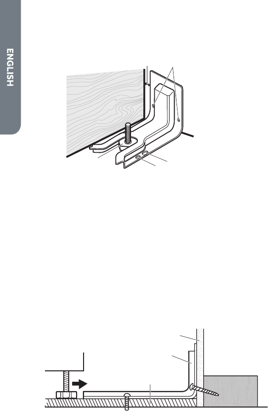
a
b
c
a Wall
b Anti-tip
Bracket
c Floor
5. Install the anti-tip bracket.
Wood
•
Using the two screws (provided) fasten the anti-tip bracket to the oor or
wall.
NOTE: The screw must enter wood or metal.
Concrete
•
Insert the sleeve anchor into the drilled holes and then insert the lag bolts
through the anti-tip bracket and into the oor or wall. The bolts must be
properly tightened as recommended for the hardware.
6. Complete the range installation following the Installation Instructions
(provided).
16