
Manual and User Guide

11
OPTION: You can install a 90º elbow (not supplied) onto the gas inlet and route the gas connections to avoid
interference when installed over an oven, with a downdraft vent, a warming drawer or other cabinetry features.
B. Complete the connection between the regulator and the shut-off valve.
C. Before testing for leaks, make sure all burner knobs are in the OFF position.
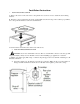
After connecting the cooktop to gas, check system for leaks with a manometer. If a manometer is not
available, turn the gas supply on to the cooktop and use a liquid leak detector at all joints and connections
to check for leaks. Tighten all connections if necessary to prevent gas leakage in the cooktop or supply line.
WARNING: Do not use a flame to check for leaks.
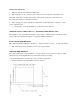
Disconnect the cooktop and its individual shut-off valve from the gas supply piping system during any
pressure testing of that system at test pressures greater than 1/2 psig (3.5 kPa).
Isolate the cooktop from the gas supply piping system by closing its individual shut-off valve during any
pressure testing of the gas supply system at test pressures equal to or less than 1/2 psig (3.5 kPa).
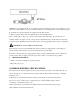
3. CONNECT ELECTRICAL
·Check to be sure the receptacle is properly grounded.
·Plug in the power cord.
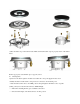
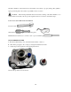
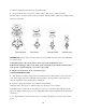
ASSEMBLE BURNERS, CHECK IGNITION
The electrode of the electronic ignition system is positioned above the surface of the burner base. Do not
remove a burner cap or touch the electrode of a burner while another is turned on. Damage or electrical
shock may occur.
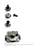
a) The electrode of the electronic ignition system is positioned above the surface of the burner
base. Do not remove a burner cap or touch the electrode of a burner while another is turned
on. Damage or electrical shock may occur.
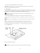
b) Place burner heads over the burner base. Make sure the hole in the burner head is properly
aligned with the electrode in the burner base.