Optical Gas Monitor Model RK60000 COSA SF6 Purity Pro Instruction Manual COSA+XENTAUR CORPORATION LOCATIONS: 84G Horseblock Rd Yaphank, NY 11980 (631) 345-3434 Fax: (631) 924-7337 7125 North Loop East Houston, TX 77028 (713) 947-9591 Fax.: (713) 947-7549 email: sales@cosaxentaur.com www.cosaxentaur.
Introduction Thank you for purchasing the Model RK60000. This instrument is a portable gas monitor to measure “Helium in N2,” “CH4 in air,” and other gas concentration and calorie (valid only to the measurement mentioned in the attached measuring gas specifications) intermittently. This instruction manual is a guidebook on how to operate the Model RK60000. Both beginner users and experienced users must read this manual and understand the contents thoroughly prior to operation.
Index 1. PARTS AND PART FUNCTIONS…………………………………………………………………..4 2. MEASURING MODE (POWER KEY)………………………………………………………………6 2-1. Basic Display for Measuring Mode and Explanation………………………….6 2-2. Procedures from Power ON to Measurement……………………………………7 2-3. Saving Data………………………………………………………………………………9 2-4. Initial Display (Self-Diagnostic Display)………………………………………….9 2-5. ERROR Message Display……………………………………………………………10 2-6. AIR CAL. CAUTION…………………………………………………………………….11 2-7.
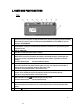
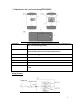
1. PARTS AND PART FUNCTIONS TOP (1) (2) (3) (4) (5) (6) (7) (8) (9) POWER key: Press this key to turn the power on until the buzzer beeps. Keep pressing the key for approximately three seconds to turn the power off. When pressing the POWER key and (7) ENTER key, you can enter the “SETTING MODE.” LCD Display: Concentration is displayed. The time, battery remainder, and measures of gas and base gas are displayed as well. LED for “SAMPLING”: The LED is on while the internal pump is working.
***Explanations in the ( ) are for use during SETTING MODE. (10) GAS IN Inlet for measuring gas. A specific absorption tube must be connected to the inlet, or the reading may go wrong. (11) REF. OUT Outlet connected to the reference gas chamber. The exhaust from the outlet must be emitted into the fresh air at atmospheric pressure. (12) GAS OUT Outlet for measuring gas sucked from the GAS IN. (13) DC6V 6VDC Interface for the specific AC adaptor. (14) REC. A jack for 0-1VDC output.
2. MEASURING MODE (POWER KEY) 2-1. Basic Display for Measuring Mode and Explanation Display Contents Status Gas Name and Base Gas Standard measuring mode. CAUTION CHECK AIR CAL. CAUTION ABNORMAL TEMP. CAUTION LOW BATT. CAUTION LOW CONTRASUT CAUTION LOW BRIGHTNESS Zero drifting might be occurring. Let the monitor sample fresh air and perform AIR CAL. Internal thermistor detects an abnormal temperature. Battery voltage is low. Replace the batteries. The interferometer sensor is getting contaminated.
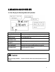
2-2. Procedures from Power ON to Measurement 1) The power is turned on by pressing the POWER key until the buzzer beeps. The initial display (self-diagnostic display) will show up as well. A display that confirms the setting will then appear. After two seconds, it will proceed to the basic display of measuring mode. Self-Diagnostic Display Confirmation Display Caution This instrument does not indicate a correct reading if the measuring gas and base gas are not selected properly.
completed, press the PUMP key and let the sample gas draw into the instrument. The color of the display will reverse while the pump is operating. *Note that the indication on display under pump operation is not measuring result. 6) After the indication on the reverse display becomes stable, the pump will stop the operation and read out the indication as a measuring result at this pump operation stop. At this pump operation, stop under the gas flow ceasing condition. This is the measuring result.
2-3. Saving Data Once the SAVE key is pressed, the buzzer will beep and the display shown right will appear. The time, data, and the measurement result are saved chronologically from No. 001 to No. 100. The saved data can be seen at “VIEW SAVED DATA” in the SETTING MODE. Also, the saved data can be deleted with “CLEAR SAVED DATA” in the SETTING MODE. 2-4.
2-5. ERROR Message Display If the problem proceeds to affect the measurement, an ERROR message (as shown to the right) will appear. ERROR message and the meanings are as follows: Contents of Display The Meanings and Required Solutions ERROR: LOW BATT. Battery voltage is too low to perform the measurement. Replace the batteries. ERROR: CONTRAST Contamination of the optic interferometer sensor is too severe to perform the measurement. Replace the sensor or have it repaired.
2-6. AIR CAL CAUTION If the temperature inside of the sensor has changed over ±10ºC from the last time the AIR CAL was performed, [CAUTION/CHECK AIR CAL] will be displayed in order to prevent zero drifting. [Measuring Gas/Base Gas] and [AIR CAL] are displayed consecutively. If the [CAUTION/CHECK AIR CAL] is displayed, perform the AIR CAL based on the procedure below: AIR CAL Procedure 1. Press the PUMP key and let it sample fresh air. 2.
Caution The pressure in the Gas Chamber changes from the atmospheric pressure while sampling the gas. As a result, the indication will not be accurate (note that if an instant pressure change occurs in the Gas Chamber or the reference Chamber, the indication might also go wrong.) If these symptoms occur, perform the AIR CAL right away. Also, be sure to note the following points: > > > > Do not plug the GAS IN or GAS OUT while the gas is feeding.
An example of measurement when the pressure of the sampling point is higher than that of the atmospheric pressure: Make an inlet (a) as drawn below. Open and shut the stop valve to feed the gas to the instrument, rather than turning the pump on and off. Read the indication when the valve is shut off and the gas flow completely stops. Flow rate at inlet (a) should be 300 to 400mL. GAS OUT should be at the atmospheric pressure and the REF. OUT should face fresh air.
3. SETTING MODE (ENTER + POWER) The SETTING MODE is for “Change the Measuring Gas,” “Adjusting the time,” and “Confirming the Saved Data.” Enter the SETTING MODE by pressing the POWER key while the ENTER key is also being pressed. Once you enter the mode, the display shown right will appear. Move the cursor (black bar) with the keys and select the item you wish to set up. Go into the item by [ENTER key].
3-2. Adjusting the Time (SET DATE/TME) The initial position of the cursor is on YEAR. Change this with the keys and fix the setting with the ENTER key. The cursor then moves to DAY. Select the DAY, MONTH, HOUR and MINUTE by the same procedures as YEAR. HOUR is displayed through a 24-hour clock. 3-3. Confirming the Saved Data (VIEW SAVED DATA) On the first line, the data number is shown. On the second and third lines, the saved data and time are displayed.
4. MAINTENANCE 4-1. Replacing the Batteries Warning > All the C-size Alkaline batteries used in the instrument should be the same kind. > Replace all four batteries at the same time. 1) 2) 3) 4) Confirm that the power is off. Remove instrument out of carrying case. Remove the old batteries and replace them with the new ones in the correct direction. Once you have replaced the batteries, place the battery cover on the bottom. 4-2.
4-4. Frequency/Standard for Replacing Parts The frequency of the replacement mentioned below is simply standard. The life of the instrument is dependent on how it is used and stored. 1) Internal Pump and Internal Tubing……………………………….2 years 2) Absorption Tube (Consumable Part)…………………………….2 years 3) Rubber Parts in Interferometer……………………………………2 years (optic element should be cleaned if necessary) 4) Main PCB……………………………………………………….……….5 years 5) Interferometer Assembly…………………………………………….
6. TROUBLE SHOOTING The trouble shootings mentioned below do not cover all problems, however those that occur most frequently are indicated to help your research for cause and solution. Symptoms Power does not turn ON. Reading is not correct. After performing AIR CAL, the reading goes up even though no gas has been fed. Causes Solutions No batteries; AC adaptor may not be connected. Insert batteries; connect AC adaptor. Polarity of the batteries is wrong. Place batteries in the correct direction.
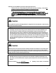
7. CAUTION OF USAGE The following caution items must be followed to maintain the performance and safety of the instrument. Danger > Specification of this instrument is based on a non-explosive structure. Do not use it in a place specified as a hazardous area. > Make any solutions for exhaust gas emitted from GAS OUT to avoid harmful gas from emission (e.g. connecting a sampling bag to GAS OUT.) > In case of instrument leakage, a mask should be worn at all times.
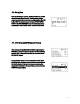
8. Definition of Terms vol%: The rate of substance occupying in some volume. The unit is indicated by percentage. ppm: The rate of substance occupying a given volume. The unit is indicated by ppm, or “parts per million.” %LEL: This is the unit when defining he Lower Explosive Limit of a combustible gas as 100%. mg/l: This is the unit of the target gas mass that is contained in one liter. The standard is under the condition of 20ºC, 101.3 kPa.
9. SPECIFICATIONS 9-1. Specifications Model Detection Principle Display Structure Measuring Method Gas-Sampling Method Outputs Data-Logging Function Operating Temp. & Humidity Operating Pressure Power Source Battery Life Dimensions Weight Model RK60000 Optical Interferometric Method Digital Display (Measuring Gas, Base Gas, Concentration, Time, etc.
10. MEASURING PRINCIPLE The Reflection ratio of gas mixture is determined by the kinds of composing gases as well as the mixture ratio. As long as the kinds of composing gases are known, the mixture ratio (concentration) can be determined by measuring the reflection ratio. The optic interferometer applied in the RK60000 displays “Interference Stripes” on the CCD. The Interference Stripes move proportional to the reflection ratio.
11. WARRANTY COSA INSTRUMENT CO. warrants gas alarm equipment manufactured and sold by us to be free from defects in materials and workmanship for a period of one year from the shipment date from COSA INSTRUMENT CO. Any parts found defective within that period will be repaired or replaced at our option, free of charge, FOB factory.
RK60000 EACH TYPE SPECIFICATIONS (TYPE– 51 ~55) 24
TYPE-51 [FOR SOLVENT GASES (vol%)] Selectable Measuring Gas and Range Measuring Gas (Display Indication) 1 2 3 4 5 6 7 8 Toluene in AIR (C7H8 in AIR) Methyl ethyl ketone in AIR (MEK in AIR) Ethyl acetate in AIR (EtAc in AIR) Xylene in AIR (C8H10 in AIR) Isopropyl alcohol in AIR (IPA in AIR) Methyl isobutyl ketone in AIR (MIBK in AIR) Methanol in AIR (CH3OH in AIR) ----------------- Measuring Range (Minimum Digit) 0~2 vol% (0.002) 0~5 vol% (0.005) AIR CAL Value Drift Amount Spec. No. 0.000 vol% 0.
TYPE-52 [FOR SOLVENT GASES (%LEL)] Selectable Measuring Gas and Range Measuring Gas (Display Indication) 1 2 3 4 5 6 7 8 Toluene in AIR (C7H8 in AIR) Methyl ethyl ketone in AIR (MEK in AIR) Ethyl acetate in AIR (EtAc in AIR) Xylene in AIR (C8H10 in AIR) Isopropyl alcohol in AIR (IPA in AIR) Methyl isobutyl ketone in AIR (MIBK in AIR) Methanol in AIR (CH3OH in AIR) ----------------- Measuring Range (Minimum Digit) 0~100 %LEL (0.2) 0~100 %LEL (0.2) AIR CAL Value Drift Amount Spec. No. 0.0 %LEL 1.
TYPE-53 [FOR FUMIGATION GASES] Selectable Measuring Gas and Range Measuring Gas (Display Indication) 1 2 3 4 5 6 7 8 Methyl bromide in AIR (CH3Br in AIR) Phosphine in AIR (PH3 in AIR) Methyl iodide in AIR (CH3I in AIR) Methyl bromide in AIR (CH3Br in AIR) Propylene oxide in AIR (PO in AIR) Sulfuryl fluoride in AIR (SO2F2 in AIR) -------------------------------- Measuring Range (Minimum Digit) 0~200 mg/l (0.2) AIR CAL Value Drift Amount Spec. No. 0.0 mg/l 1.7 mg/l SPE- 1405 0~50 mg/l (0.
TYPE-54 [FOR GAS PURITY] Selectable Measuring Gas and Range Measuring Gas (Display Indication) 1 2 3 4 5 6 7 8 Helium in AIR (He in AIR) Neon in AIR (Ne in AIR) Hydrogen in AIR (H2 in AIR) Methane in AIR (CH4 in AIR) Carbon dioxide in AIR (CO2 in AIR) Ammonia in N2 (NH3 in N2) Hydrogen in N2 (H2 in N2) Hydrogen in CO2 (H2 in CO2) Measuring Range (Minimum Digit) 0~100 vol% (0.05) 0~100 vol% (0.1) 0~100 vol% (0.1) 0~100 vol% (0.1) 0~100 vol% (0.1) 0~100 vol% (0.2) 0~100 vol% (0.1) 0~100 vol% (0.
TYPE-55 [FOR ANAESTHETIC GASES] Selectable Measuring Gas and Range Measuring Gas (Display Indication) 1 2 3 4 5 6 7 8 Halothane in O2 (HALOTHANE in O2) Isoflurane in O2 (ISOFLURANE in 02) Sevoflurane in O2 (SEVOFLURANE in O2) Desflurane in O2 (DESFLURANE in O2) Halothane in AIR (HALOTHANE in AIR) Isoflurane in AIR (ISOFLURANE in AIR) Sevoflurane in AIR (SEVOFLURANE in AIR) Desflurane in AIR (DESFLURANE in AIR) Measuring Range (Minimum Digit) 0~6 vol% (0.01) 0~8 vol% (0.01) 0~10 vol% (0.
TYPE-56 [FOR CALORIE MEASUREMENT] Selectable Measuring Gas and Range Measuring Gas (Display Indication) 1 2 3 4 5 6 7 8 Propane in AIR (PROPANE in AIR) Propane in AIR (PROPANE in AIR) Butane in AIR (BUTANE in AIR) Butane in AIR (BUTANE in AIR) Propane in AIR (PROPANE in AIR) Propane in AIR (PROPANE in AIR) Butane in AIR (BUTANE in AIR) Butane in AIR (BUTANE in AIR) Measuring Range (Minimum Digit) 0~100 MJ/m3 Gross (0.1) 0~100 MJ/m3 Net (0.1) 0~100 MJ/m3 Gross (0.1) 0~100MJ/m3 Net (0.
TYPE-58 [FOR SF6 MEASUREMENT] Selectable Measuring Gas and Range Measuring Gas (Display Indication) 1 2 3 4 5 6 7 8 Sulfur Hexafluoride (SF6) Measuring Range (Minimum Digit) 0~100 vol% (0.1) AIR CAL Value Drift Amount Spec. No. 0.0 vol% 1.0 vol% SPE- 1414 Interferometer Type: Type 7.5MM Indication Accuracy: ± (Indication Value – AIR CAL Value) x 0.03 ± Drift Amount AIR CAL Value: Concentration indicated on the display when AIR CAL key is pressed.
Gas Purity Indicator for SF6 (RK60000-SF6) Simple Instructional Manual SECTION 1. POWER ON 1-1. Make sure that the change over cock (measuring gas/air) is turned sideways. 1-2. Press the power button on the Model RK60000 until beeping.
SECTION 2. ZERO ADJUSTMENT 2-1. Adjust the flow rate to be 0.2±0.04 L/min at flow meter “B” (located right on the panel). 2-2. Verify that the indication value has been stable and press the AIR CAL button until it starts to beep.
SECTION 3. PREPARATIONS FOR GAS SAMPLING AND MEASURING 3-1. Connect the sampling tube to the gas inlet “GAS IN” on the panel and apply the sampling gas (SFG) from the sampling point. The sampling gas pressure should then be less than 0.7 MPa. 3-2. Make sure that the pressure regulator on the panel is set 0.1±0.02MPa. Regulator adjustment must be done at step 4. SECTION 4. START MEASURING 4-1.Turn the change over cock (measuring gas/air) vertical. The unit will begin to measure.
The higher that the flow rate of meter “A” is set, the sooner its indication will be stable. Also, since the instrument has air in the internal piping, regulator, or sampling tube, we recommend adjusting the flow monitor “A” so that it is more than 0.8 L/min every first turn when measuring. SECTION 5. OTHER OPERATION 5-1. Incase of checking zero or suspending measuring, turn the change over cock (measuring gas/air) sideways. 5-2. It is enough for further measuring to set flow meter “A” 0.
Operated by AC Adaptor Connect the plug of the AC adaptor to the connector. *1: Exclusive use for the model RK60000, an optional accessory. *2: The connector is on the left side of the instrument. Operated by Dry Cell Install four alkaline batteries. Take out The model RK60000 from the carrying case. The battery holder is at the bottom of the unit. Unscrew the screw with a coin or screw driver and pull the battery cover from the bottom case.