ROBOTC VEX ROBOTICS COMPETITION ROBOTC Software Inspection Guide with Additional Help Documentation VEX Cortex Software Inspection Steps: 1. Cortex Firmware Inspection using ROBOTC 2. Testing Cortex Robots using VEXnet VEX PIC Software Inspection Steps: 1A. PIC Firmware Inspection using ROBOTC (Recommended Method) 1B. PIC Firmware Inspection using the IFI Loader 2A. Testing PIC Robots using the 75MHz Crystals 2B. Testing PIC Robots using the VEXnet Upgrade Additional Help Documents: 1.
ROBOTC VEX ROBOTICS COMPETITION Cortex Firmware Inspection Using ROBOTC This document is part of a software inspection guide for VEX Cortex based robots. Use this document to determine what versions of the Master firmware and ROBOTC user firmware are loaded on a robot. For the most up-to-date firmware files download the latest version of ROBOTC for Cortex and PIC at www.robotc.net.
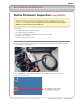
ROBOTC VEX ROBOTICS COMPETITION Cortex Firmware Inspection Using ROBOTC (cont.) 3. Verify that the Platform Type in ROBOTC is set to VEX 2.0 Cortex. 4. Turn the VEX Cortex ON. 5. Select Software Inspection from the Robot menu in ROBOTC.
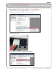
ROBOTC VEX ROBOTICS COMPETITION Cortex Firmware Inspection Using ROBOTC (cont.) 6. The VEX Cortex Software Inspection screen will open, and display information about your VEX Cortex configuration. The Cortex Master CPU Integrity section displays the Firmware Version of the Master CPU Firmware, and whether it is up to date. If it is not up to date, you can download the Master Firmware by going to Robot > Download Firmware > Master CPU Firmware > Standard File.
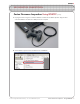
ROBOTC VEX ROBOTICS COMPETITION Cortex Firmware Inspection Using ROBOTC (cont.) 7. Unplug the Cortex. Plug one end of the USB A-to-A cable into the VEXnet Joysticks. Plug the other end of the USB A-to-A cable into a USB port on the computer. 8. Select Software Inspection from the Robot menu in ROBOTC.
ROBOTC VEX ROBOTICS COMPETITION Firmware Inspection Using ROBOTC (cont.) 9. The VEX Cortex Software Inspection screen will open, and display information about your VEXnet Joystick configuration. The VEXnet Joystick Integrity section displays the Firmware Version of the VEXnet Joystick and whether it is up to date. If it is not up to date, you can download the VEXnet Joystick Firmware by going to Robot > Download Firmware > VEXnet Joystick Firmware > Standard File.
ROBOTC VEX ROBOTICS COMPETITION Testing VEX Cortex Robots using VEXnet This document is an inspection guide for VEX Cortex based robots. Use this document to test if a robot is competition ready. Method I. Using the ROBOTC Competition Debug Window You will need: • A VEX Cortex and VEXnet Joysticks that have been paired/synced • A computer with ROBOTC for Cortex and PIC 2.32 (or later) installed • A VEX Programming Kit • An object to prop the robot up, off of its wheels 1.
ROBOTC VEX ROBOTICS COMPETITION Testing VEX Cortex Robots using VEXnet (cont.) 3. Turn on the VEX Cortex and VEXnet Joysticks and allow them to pair. 4. Open ROBOTC for Cortex and PIC 5. Verify that the Platform Type in ROBOTC is set to VEX 2.0 Cortex.
ROBOTC VEX ROBOTICS COMPETITION Testing VEX Cortex Robots using VEXnet (cont.) 6. Establish a connection with the Cortex by going to the Robot menu and selecting Debugger. 7. After a connection has been established and the Program Debug window appears, go to Robot > Debug Windows and select Competition Control. 8. The VEXnet Competition Control debug window will appear.
ROBOTC VEX ROBOTICS COMPETITION Testing VEX Cortex Robots using VEXnet (cont.) 9. Press the Start button on the Program Debug window. Note: After pressing the Start button, the robot will automatically go into User Control mode. 10. To test the robot’s autonomous mode, press the Autonomous button on the VEXnet Competition Control window. The code for autonomous mode will run once, until it is finished, or until you press the Disabled button on the VEXnet Competition Control window.
ROBOTC VEX ROBOTICS COMPETITION Testing VEX Cortex Robots using VEXnet (cont.) Method II. Using the VEXnet Competition Switch You will need: • A VEX robot and transmitter with paired VEXnet Upgrades • A VEXnet Competition Switch • An Ethernet Cable • An object to prop the robot up, off of its wheels 1. Connect the VEXnet Joysticks to the VEXnet Competition Switch using an ethernet cable. 1a. Connect to the Joysticks Plug one end of the ethernet cable into the COMPETITION port on the VEXnet Joysticks.
ROBOTC VEX ROBOTICS COMPETITION Testing VEX Cortex Robots using VEXnet (cont.) 3. Prop the robot up, so that its wheels are no longer touching a surface. 4. Turn on the VEX Cortex and VEXnet Joysticks and allow them to pair. To test the robot’s autonomous mode, verify that the DRIVER/AUTONOMOUS switch is set to AUTONOMOUS and change the ENABLE/DISABLE switch to ENABLE. The code for the autonomous period will run once, until it is finished, or until it is disabled on the VEXnet Competition Switch.
ROBOTC VEX ROBOTICS COMPETITION Testing VEX Cortex Robots using VEXnet (cont.) Useful Information - The VEX Remote Screen The ROBOTC Competition Templates are pre-programmed to display status information to the VEX LCD Screen. Even if you don’t have the VEX LCD Screen attached to your robot, you can use the ROBOTC VEX Remote Screen to view the information (along with any other information you choose to display yourself). To open the VEX Remote Screen, first open the ROBOTC Debugger.
ROBOTC VEX ROBOTICS COMPETITION VEX PIC Firmware Inspection Using ROBOTC This document is part of a software inspection guide for VEX PIC based robots. Use this document to determine what versions of the IFI Master firmware and ROBOTC user firmware are loaded on a robot. For the most up-to-date firmware files download the latest version of ROBOTC for Cortex and PIC at www.robotc.net. You will need: • Your VEX PIC Microcontroller with Battery • A computer with ROBOTC for Cortex and PIC 2.
ROBOTC VEX ROBOTICS COMPETITION VEX PIC Firmware Inspection Using ROBOTC (cont.) 3. Verify that the Platform Type in ROBOTC is set to VEX 0.5 Microchip. 4. If the VEX Microcontroller is not already turned on, turn it on now. 4. Turn the VEX Microcontroller on Flip the small switch on your VEX Microcontroller to turn your robot on, if it is not on already. Make sure that a charged battery pack is connected. 5. Different features and options are available in ROBOTC depending on what mode is set.
ROBOTC VEX ROBOTICS COMPETITION VEX PIC Firmware Inspection Using ROBOTC (cont.) 6. Establish a connection to the VEX Microcontroller by going to the Robot menu and selecting Debugger. Note: The IFI Loader software and other VEX programming solutions also establish connections with the VEX Microcontroller. If any of the other software programs are open, close them to ensure that ROBOTC will be able to connect to the robot. 7.
ROBOTC VEX ROBOTICS COMPETITION Firmware Inspection Using IFI Loader This document is part of a software inspection guide for VEX v0.5 (75 MHz crystal) and VEX v1.5 (VEXnet Upgrade) microcontroller-based robots. Use this document to determine what versions of the IFI Master firmware and ROBOTC user firmware are loaded on a robot. You will need: • Your VEX Microcontroller • A computer with the IFI Loader software installed (available at http://www.vexforum.com/wiki/index.
ROBOTC VEX ROBOTICS COMPETITION Firmware Inspection Using IFI Loader (cont.) 2. Open the IFI Loader software from your Desktop or Start menu. The IFI Loader can be downloaded from http://www.vexforum.com/wiki/index.php/Software_Downloads. 3. Once the IFI Loader software opens, select the port on your computer that the Programming Kit is connected to by going to PortSettings and selecting the appropriate COM Port.
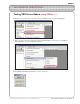
ROBOTC VEX ROBOTICS COMPETITION Firmware Inspection Using IFI Loader (cont.) Information - Windows Device Manager To open the Windows Device Manager right-click on “My Computer” and select “Properties”. Then select the “Hardware” tab and choose “Device Manager”. Click on the “+” sign next to “Ports (COM & LPT)” to expand it. Look for the menu item described as a USB-to-Serial Comm Port and make note of the COM number following it in parenthesis.
ROBOTC VEX ROBOTICS COMPETITION Firmware Inspection Using IFI Loader (cont.) 5. Once the Terminal Window is open, turn the VEX Microcontroller on. If it is already turned on, turn it off, and then back on. 5. Power Cycle the VEX Microcontroller Flip the small switch on your VEX Microcontroller to turn your robot on. If it is already on, turn it off, and then back on. 6. The Terminal Window will display both the master and ROBOTC user firmware. The VEX Master firmware version should be at least 10.
ROBOTC VEX ROBOTICS COMPETITION Testing VEX PIC Robots with the 75 MHz Crystals This document is an inspection guide for VEX v0.5 microcontroller-based robots. Use this document to test if a robot using the 75 MHz crystals is competition ready. You will need: • A VEX robot and transmitter with matching 75 MHz crystals • A stopwatch • An object to prop the robot up, off of its wheels 1. Turn both the VEX Microcontroller and Radio Control Transmitter OFF. 2.
ROBOTC VEX ROBOTICS COMPETITION Testing VEX PIC Robots with the 75MHz Crystals (cont.) 3. Turn on the VEX Microcontroller. 4. Turn on the Radio Control Transmitter and observe the robot. You will need to use the transmitter joysticks and buttons to test the user control period. After turning on the transmitter, robots using the Competition Template will immediately run their autonomous code for the amount of time specified within the template (20 seconds by default).
ROBOTC VEX ROBOTICS COMPETITION Testing VEX PIC Robots with the 75MHz Crystals (cont.) Useful Information - The VEX Remote Screen The ROBOTC Competition Templates are pre-programmed to display status information to the VEX LCD Screen. Even if you don’t have the VEX LCD Screen attached to your robot, you can use the ROBOTC VEX Remote Screen to view the information (along with any other information you choose to display yourself). To open the VEX Remote Screen, first open the ROBOTC Debugger.
ROBOTC VEX ROBOTICS COMPETITION Testing VEX PIC ROBOTS with the VEXnet Upgrade This document is an inspection guide for VEX v1.5 microcontroller-based robots. Use this document to test if a robot using the VEXnet Upgrade is competition ready. Method I. Using the ROBOTC Competition Debug Window You will need: • A VEX robot and transmitter with paired VEXnet Upgrades • A computer with ROBOTC for Cortex and PIC 2.
ROBOTC VEX ROBOTICS COMPETITION Testing VEX PIC Robots with the VEXnet Upgrade (cont.) 3. Turn on the VEX robot and transmitter. Allow the VEXnet Upgrades to pair. 4. Open ROBOTC for Cortex and PIC 5. Verify that the Platform Type in ROBOTC is set to VEX 0.5 Microchip.
ROBOTC VEX ROBOTICS COMPETITION Testing VEX PIC Robots with the VEXnet Upgrade (cont.) 6. Establish a connection to the VEX Microcontroller by going to the Robot menu and selecting Debugger. 7. After a connection has been established and the Program Debug window appears, go to Robot > Debug Windows and select Competition Control. 8. The VEXnet Competition Control debug window will appear.
ROBOTC VEX ROBOTICS COMPETITION Testing VEX PIC Robots with the VEXnet Upgrade (cont.) 9. Press the Start button on the Program Debug window. Note: After pressing the Start button, the robot will automatically go into User Control mode. 10. To test the robot’s autonomous mode, press the Autonomous button on the VEXnet Competition Control window. The code for autonomous mode will run once, until it is finished, or until you press the Disabled button on the VEXnet Competition Control window.
ROBOTC VEX ROBOTICS COMPETITION Testing VEX PIC Robots with the VEXnet Upgrade (cont.) Method II. Using the VEXnet Competition Switch You will need: • A VEX robot and transmitter with paired VEXnet Upgrades • A VEXnet Competition Switch • An Ethernet Cable • An object to prop the robot up, off of its wheels 1. Connect the VEXnet Upgrade on the Radio Control Transmitter to the VEXnet Competition Switch using the VEX ethernet cable. 1a.
ROBOTC VEX ROBOTICS COMPETITION Testing VEX PIC Robots with the VEXnet Upgrade (cont.) 3. Prop the robot up, so that its wheels are no longer touching a surface. 4. Turn on the VEX robot and transmitter. Allow the VEXnet Upgrades to pair. To test the robot’s autonomous mode, verify that the DRIVER/AUTONOMOUS switch is set to AUTONOMOUS and change the ENABLE/DISABLE switch to ENABLE.
ROBOTC VEX ROBOTICS COMPETITION Testing VEX PIC Robots with the VEXnet Upgrade (cont.) Useful Information - The VEX Remote Screen The ROBOTC Competition Templates are pre-programmed to display status information to the VEX LCD Screen. Even if you don’t have the VEX LCD Screen attached to your robot, you can use the ROBOTC VEX Remote Screen to view the information (along with any other information you choose to display yourself). To open the VEX Remote Screen, first open the ROBOTC Debugger.
ROBOTC VEX ROBOTICS COMPETITION ROBOTC Programming Competition Templates This document is part of a software inspection guide for VEX based robots. Use this document to learn how to use the “Competition Template” or “Driver Skills Template” included with ROBOTC. For the most up-to-date versions of the templates (and ROBOTC) download the latest version of ROBOTC for Cortex and PIC at www.robotc.net. You will need: • A computer with ROBOTC for Cortex and PIC 2.32 or later installed (available at www.
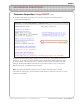
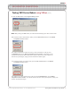
ROBOTC VEX ROBOTICS COMPETITION ROBOTC Programming Competition Templates (cont.) 3. A new file named Competition.c will appear. Before making any changes to the template, go to File, select Save As... and save this program in a location and under a name you will remember. Shown below are the contents of the Competition.c file with brief descriptions, but with the comments removed. Additional details are available throughout the document.
ROBOTC VEX ROBOTICS COMPETITION ROBOTC Programming Competition Templates (cont.) Setting up Competition Control and Timing In ROBOTC, competition programming is completely user customizable, so no jumpers are required for testing. By adjusting the following commands, the templates can be adapted to work in any VEX supported competition.
ROBOTC VEX ROBOTICS COMPETITION ROBOTC Programming Competition Templates (cont.) Pre-Autonomous Period Place your initialization code inside this function. During the pre-autonomous period, code can be executed to configure your robot before the actual competition begins. Valid code for this section includes tasks such as clearing encoders, reflecting motors, and setting initial servo positions.
ROBOTC VEX ROBOTICS COMPETITION ROBOTC Programming Competition Templates (cont.) User Control Period Place your user control code inside this task. During the user controlled period, the robot accepts commands from the VEXnet Joysticks (VEX Cortex based robots) or the Radio Control Transmitter (VEX PIC based robots). This segment of code typically executes immediately after the autonomous period ends.
ROBOTC VEX ROBOTICS COMPETITION ROBOTC Programming Competition Templates (cont.) Sample Competition Template with User Code #pragma config(Sensor, in1, bumper, sensorTouch) //*!!Code automatically generated #pragma platform(VEX) Motors and Sensors configured using the ROBOTC Motors and Sensors setup window will automatically be added as pragma statements at the top of the program.
ROBOTC VEX ROBOTICS COMPETITION ROBOTC Programming Competition Templates (cont.) Part II. Using the ROBOTC Driver Skills Template Using the ROBOTC Driver Skills Template is very similar to using the ROBOTC Competition Template.
ROBOTC VEX ROBOTICS COMPETITION ROBOTC Programming Competition Templates (cont.) Shown below are the contents of the DriverSkills.c file with brief descriptions, but with the comments removed and additional spacing added. Additional details can be found in Part I of this document.
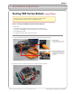
ROBOTC Setup Driver Installation In this lesson, you will learn how to install the USB-to-Serial Cable driver. Make sure you have sufficient security privileges to install drivers on the computer before you begin. You will need: 1. A ROBOTC for IFI Installation CD or an Internet connection 2. A VEX USB-to-Serial cable 1. Plug the USB connector end into your computer. 1. Connect the cable Plug the USB end of the cable into the computer.
ROBOTC Setup Driver Installation 2. Cancel any automatic installation prompts that may appear, such as the “Found New Hardware Wizard” Window. Instead, run the driver installation program manually from the ROBOTC for IFI CD-ROM or download and run the driver from the ROBOTC.net website. For downloading instructions, see step 3. 2a. Cancel any installation wizard The driver installation does not require the use of the “Found New Hardware Wizard”. 2b.
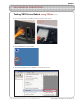
ROBOTC Setup Driver Installation 3. If you download the driver from ROBOTC.net, the installation file will need to be extracted before you can start the installation process. Extract the “prolific_usb_driver” file by right-clicking its icon, selecting “Extract All...”, and proceeding through the following steps. Once complete, run the “SETUP” file and follow the its instructions to finish installing the USB-to-Serial driver. 3a.
ROBOTC Setup Driver Installation 4. Follow the installation prompts to complete the installation. 4a. Follow prompts Complete the installation according to the onscreen instructions. 4b. Finish the installation Unplug the USB-to-Serial cable and plug it back in to complete the installaton.
ROBOTC Setup VEX Cortex Configuration over USB The VEX Cortex is a fully programmable device, and is what enables you to incorporate motors, sensors, an LCD screen, and remote control signals all in one robot. Inside of the Cortex, there are two separate processors; a user processor handles all of the ROBOTC programming instructions, and a master processor controls lower-level operations, like motor control and VEXnet communication.
ROBOTC Setup VEX Cortex Configuration over USB (cont.) 2. Specify that you are using the Cortex and how it is connected to your computer in ROBOTC. 2a. Detailed Preferences... Go to View > Preferences and select Detailed Preferences... 2b. Platform Settings Make sure that the Platform tab is selected on the ROBOTC Preferences window. Next, specify the Natural Language (VEX Cortex) as your Platform Type.
ROBOTC Setup VEX Cortex Configuration over USB (cont.) 3. The VEX Cortex Download Method controls how ROBOTC downloads firmware and programs to your Cortex, as well as what types of connections your Cortex checks for when it is powered on. Confirm that your VEX Cortex Download Method is set to Download Using VEXnet or USB or Download Using USB Only.
ROBOTC Setup VEX Cortex Configuration over USB (cont.) 4. Go to Robot > Download Firmware > Master CPU Firmware and select Standard File to download the latest Master CPU Firmware to your robot. 4. Download Progress A Download Progress window will appear and begin the download process. When the window closes, the firmware download is complete. A ROBOTC Message will appear, and remind you to also download the ROBOTC Firmware.
ROBOTC Setup VEX Cortex Configuration over USB (cont.) 5. The ROBOTC Firmware enables you to download ROBOTC programs to your robot and utilize the various debug windows. Go to Robot > Download Firmware > ROBOTC Firmware and select Standard File to download the ROBOTC Firmware to your robot. 5. Download Progress A Download Progress window will appear and begin the download process. When the window closes, the firmware download is complete.
ROBOTC Setup VEXnet Joystick Configuration in ROBOTC The VEXnet Joystick enables more than just the remote control of your robot. It also provides the wireless communication link between your computer and the VEX Cortex, enabling you to wirelessly download firmware, programs and run the ROBOTC debugger. In this document, you will learn how to configure VEXnet Joystick using ROBOTC. This document is broken into 3 sections: 1. Downloading Firmware to the VEXnet Joystick 2.
ROBOTC Setup VEXnet Joystick Configuration in ROBOTC (cont.) 2. Connect the VEXnet Joystick to your computer using the USB A-to-A cable and turn it ON. 2a. Connect the VEXnet Joystick Use the USB A-to-A cable to connect your VEXnet Joystick to your computer. Note: The VEXnet light should turn green. 2b. Turn the VEXnet Joystick ON Switch the VEXnet Joystick to the ON postion. Note: The Joystick light should turn green.
ROBOTC Setup VEXnet Joystick Configuration in ROBOTC (cont.) 3. Go to Robot > Download Firmware > VEXnet Joystick Firmware and select Standard File to download the latest VEXnet Joystick Firmware to the controller. 3. Download Progress A Download Progress window will appear and begin the download process. When the window closes, the firmware download is complete.
ROBOTC Setup VEXnet Joystick Configuration in ROBOTC (cont.) Section 2: Creating a wireless link betwen the VEXnet Joystick and VEX Cortex In this section, you will learn how to pair a VEX Cortex Microcontroller to a VEXnet Joystick, allowing them to communicate over VEXnet. This section assumes that you have already updated the master firmware on the VEX Cortex and VEXnet Remote Control. VEXnet is an 802.11 WiFi communication system between the VEX Cortex and VEXnet Remote Control.
ROBOTC Setup VEXnet Joystick Configuration in ROBOTC (cont.) 2. Tether the USB port on the VEXnet Joystick to the USB port on the Cortex using a USB A-to-A cable. 2a. VEXnet Joystick USB Port Plug one end of the USB A-to-A cable into the USB port on the VEXnet Joystick. 2b. VEX Cortex USB Port Plug the other end of the USB A-to-A cable into the USB port on the VEX Cortex. 3. Power the Cortex ON.
ROBOTC Setup VEXnet Joystick Configuration in ROBOTC (cont.) 4. Turn the Cortex OFF. 5. Remove the USB A-to-A cable from the VEXnet Joystick and Cortex. 6. Insert VEXnet USB Keys into both the VEXnet Joystick and Cortex. 6. VEXnet USB Keys Insert VEXnet USB Keys into the VEXnet Joystick and Cortex. Note: It does not matter which VEXnet USB Key you insert into the Cortex versus the VEXnet Joystick.
ROBOTC Setup VEXnet Joystick Configuration in ROBOTC (cont.) 7. Power the Cortex and Joystick ON. After roughly 15 seconds, the ROBOT and VEXnet LED’s will blink green, indicating that the VEXnet communication link has been established. 7a. Turn the Cortex ON 7b. Turn the VEXnet Joystick ON 7c. Status LEDs After roughly 15 seconds, the ROBOT and VEXnet status LEDs will start quickly blinking green.
ROBOTC Setup VEXnet Joystick Configuration in ROBOTC (cont.) Section 3: Calibrating the VEXnet Joystick Values This section contains the procedure for calibrating the VEXnet Remote Control joysticks. Some steps are time-sensitive, so it’s recommended that you read through the instructions once before following along. The VEXnet Remote Control includes two joysticks (each having an X and Y-axis), 8 buttons on the front, and 4 additional trigger buttons on the top.
ROBOTC Setup VEXnet Joystick Configuration in ROBOTC (cont.) 2. Press and hold the 6U trigger button. 2. Press and hold the 6U trigger button 3. While keeping the 6U trigger button pressed in, use your Allen wrench or paper clip to press in the internal CONFIG button until the JOYSTICK LED blinks red and green. 3a. Press and the CONFIG button While still pressing in the 6U trigger button, use an Allen wrench or paper clip to press in the CONFIG button. 3b.
ROBOTC Setup VEXnet Joystick Configuration in ROBOTC (cont.) Important - Time Sensitive Instructions There is a 10 second time limit to complete steps 4 and 5. If they are not completed in time, the calibration process will timeout and the VEXnet LED will blink red briefly. 4. Move both joysticks through their full ranges of motion. When the remote control detects that the joysticks have been fully rotated, the JOYSTICK LED stops blinking red and green, and switches to a solid green. 4a.
ROBOTC Setup VEXnet Joystick Configuration in ROBOTC (cont.) 5. Press the 8U button to save the new calibration. 5. Save Press the 8U button to save the joystick calibration on your remote control. The JOYSTICK LED will blink green for a few seconds. Additional Information • If the calibration is not saved, the process will timeout after 10 seconds and the VEXnet LED will blink red. • To cancel a calibration, press the 7U button.
ROBOTC Setup VEXnet Joystick Configuration in ROBOTC (cont.) Troubleshooting Issue: Slow blinking green ROBOT light on the Cortex Solution: Download the Cortex Master Firmware using ROBOTC. Issue: Slow blinking ROBOT green light on the VEXnet Joystick Solution: Push and hold CONFIG button for about 5 seconds, until the status LEDs starts blinking green. Release it, wait for another 5 seconds, and then turn the VEXnet Joystick OFF and then back ON.
ROBOTC Setup Master Firmware Download Instructions In this document, you will learn how to download the IFI Master CPU Firmware to the VEX Microcontroller. What is the Master Firmware? The VEX Microcontroller contains two processors: a user processor that handles all of the ROBOTC instructions, and a master processor that handles lower-level operations like motor control and radio communication.
ROBOTC Setup Master Firmware Download Instructions (cont.) 2. Power the VEX Microcontroller and connect it to your computer using the orange USB-to-Serial programming cable. 2a. Power the VEX Microcontroller Connect the VEX Microcontroller to a charged 7.2V battery and turn it ON. 2b. Connect the VEX to the Computer Use the orange USB-to-Serial programming cable to connect the VEX to your computer. If you are using the VEXnet Microcontroller Upgrade, temporarily unplug it from the SERIAL port.
ROBOTC Setup Master Firmware Download Instructions (cont.) 3. Open ROBOTC for IFI. 3. Open ROBOTC for IFI Open ROBOTC for IFI from your Desktop or Start Menu. 4. Download the master firmware to the VEX Microcontroller. 4a. Download IFI Master CPU Firmware Go to Robot and select Download IFI Master CPU Firmware. 4b. Select the Master Firmware File Choose the file that begins with VEX_MASTER and has the highest version number available. Press Open to start the download.
ROBOTC Setup Master Firmware Download Instructions (cont.) 4c. OK the Information Window An information window may appear with details about the VEXnet communication system. Press OK to close it. 4d. IFI Controller Firmware Download Status The IFI Controller Firmware Download Status will appear and begin the download. 4e. ROBOTC User Firmware Reminder Once the master firmware is finished downloading, a ROBOTC Message window will appear, reminding you to download the ROBOTC user firmware.
ROBOTC Setup Download ROBOTC User Firmware In this lesson, you will learn how to connect your VEX Microcontroller to the PC and load the ROBOTC User firmware onto it, allowing the robot to run ROBOTC programs. You will need: • Your VEX Microcontroller • A computer with ROBOTC for IFI 2.0 or later installed • A VEX Programming Kit (1 USB-to-Serial cable, 1 VEX Robot Interface (“telephone”) Cable, 1 VEX Programming Module) 1.
ROBOTC Setup Download ROBOTC User Firmware (cont.) 2. Plug the free USB connector end of the Programming cable into a USB port on your computer. Plug the other unconnected end of the cable into the “SERIAL” port of your VEX Microcontroller. 2a. Connect USB to PC Plug the remaining USB connector on the USB-to-Serial Cable into the PC. 2b. Connect “phone” to VEX Plug the loose RJ25 “phone” connector into the SERIAL port on the VEX Microcontroller.
ROBOTC Setup Download ROBOTC User Firmware (cont.) 3. If the VEX Microcontroller is not already turned on, turn it on now. 3. Turn the VEX Microcontroller on Flip the small switch on your VEX Microcontroller to turn your robot on, if it is not on already. Make sure that a charged battery pack is connected. 4. Open ROBOTC for IFI and make sure it is configured to work with the VEX Microcontroller. 4a. Open ROBOTC for IFI Open ROBOTC for IFI from your Desktop or Start Menu. Checkpoint.
ROBOTC Setup Download ROBOTC User Firmware (cont.) ROBOTC Registration If you have not yet registered your copy of ROBOTC, the window below will appear when you run ROBOTC. Follow the instructions printed on your CD case or online at www.robotc.net to activate your copy of ROBOTC. Information Box A message that ROBOTC commands are unavailable may also appear. This is normal. Click OK to acknowledge and dismiss the message.
ROBOTC Setup Download ROBOTC User Firmware (cont.) 5. Now that ROBOTC is open, go to the View menu and select Preferences. A new window with a Platform tab appears. Select the platform type and COM port for your robot. 5a. Open Preferences window Select View > Preferences to open the ROBOTC Preferences window. 5b. Choose Platform Type Select Innovation First (IFI) VEX as the Platform Type. 5c. Choose VEX Communications Port Select the correct COM port.
ROBOTC Setup Download ROBOTC User Firmware (cont.) 7. The Select VEX firmware file window appears. The VEX firmware file starts with “VEX” and has a number. If more than one file starts with “VEX”, choose the one with the highest number. Choose Open to start downloading the VEX firmware. 7a. Select the firmware Choose the VEX firmware file with the highest number following it. 7b. Open the file Click Open to begin downloading the firmware file you selected. 7c.
ROBOTC Setup Download ROBOTC User Firmware (cont.) End of Section Your robot is now ready to run ROBOTC programs. The firmware you downloaded in this lesson tells the robot how to “speak” ROBOTC. Any time you want to switch programming languages, you may be required to load the appropriate firmware for that language. In the next lesson, you will download a program to the robot.
ROBOTC Setup VEXnet Upgrade Installation Instructions In this document, you will learn how to install the VEXnet Upgrades on both the VEX Microcontroller and the Radio Control Transmitter. This document assumes that you have already downloaded the Master Firmware to your VEX Microcontroller. What is VEXnet? VEXnet is an 802.11 WiFi replacement for the crystal-based communication system between the VEX Microcontroller and Radio Control Transmitter.
ROBOTC Setup VEXnet Upgrade Installation Instructions (cont.) 2. Attach the VEXnet Upgrade to the top of the Microcontroller. 2a. Collect the Parts Gather the following parts before moving on: 1 1 8 4 1 Microcontroller VEXnet Microcontroller Upgrade 3/4” 8-32 Screws 1/2” Standoffs 7.2V Battery 2b. Secure Components to the VEXnet Upgrade Use four of the screws to attach the 1/2” standoffs to the VEXnet upgrade. 2c.
ROBOTC Setup VEXnet Upgrade Installation Instructions (cont.) 3. Power the Microcontroller and VEXnet upgrade with the 7.2V battery. 3a. Power the VEXnet Connect the battery to the VEXnet Upgrade. 3b. Power the Microcontroller Connect the battery wire coming from the VEXnet Upgrade to the Microcontroller. The ON/OFF switch on the Microcontroller controls the power to the Microcontroller and the VEXnet Upgrade. 4. Connect the yellow VEXnet cable to the SERIAL port on the Microcontroller.
ROBOTC Setup VEXnet Upgrade Installation Instructions (cont.) 5. Connect a VEXnet USB adapter to the VEXnet Microcontroller Upgrade. 5a. Apply the Velcro Attach the Velcro loop piece (fuzzy) to the USB adapter and the hook piece (bristly) to the Microcontroller so they will align once the USB adapter is inserted into the VEXnet Upgrade. This will ensure that the adapter will not get disconnected while the robot is running. Note: It does not matter which VEXnet USB adapter you use. 5b.
ROBOTC Setup VEXnet Upgrade Installation Instructions (cont.) Part II. Installing the VEXnet Upgrade on the Transmitter 1. Begin by removing the battery door and crystal on the back of the Transmitter. 1a. Remove the Battery Door Slide the battery door down to remove it from the Transmitter. The VEXnet Upgrade will replace it. 1b. Remove the Crystal Pull the crystal from the back of the Transmitter to remove it. 2. Place the 9.6V rechargeable battery in the battery compartment. 2.
ROBOTC Setup VEXnet Upgrade Installation Instructions (cont.) 3. Power the Transmitter and VEXnet upgrade with the 9.6V battery. 3a. Power the VEXnet Connect the battery to the VEXnet Upgrade. 3b. Power the Transmitter Connect the battery wire coming from the VEXnet Upgrade to the Transmitter. 3c. Controlling the Power The ON/OFF switch on the VEXnet Upgrade controls the power to the Transmitter and the VEXnet Upgrade, but the Transmitter must also be turned on to send and receive data.
ROBOTC Setup VEXnet Upgrade Installation Instructions (cont.) 4. Install the VEXnet Transmitter Upgrade in place of the battery door. 4a. Use Caution... Be careful to route the wires so they won’t get pinched. 4b. Install the VEXnet Upgrade Slide the VEXnet Upgrade into the Transmitter to secure it. 5. Connect the short yellow wire on the VEXnet Upgrade to the TETHER PORT on the Transmitter.
ROBOTC Setup VEXnet Upgrade Installation Instructions (cont.) 6. Connect a VEXnet USB adapter to the VEXnet Transmitter Upgrade. 6a. Apply the Velcro Attach the Velcro loop side (fuzzy) to the USB adapter and insert the hook side (bristly) into the slot on the the VEXnet adapter so they will align once the USB adapter is inserted. Note: It does not matter which VEXnet USB adapter you use. 6b.
ROBOTC Setup VEXnet Upgrade Installation Instructions (cont.) Part III. Manually Pairing the Microcontroller and Transmitter VEXnet Upgrades Important Note: Bundled Microcontroller and Transmitter VEXnet Upgrades are preconfigured to automatically establish a link with each other.
ROBOTC Setup VEXnet Upgrade Installation Instructions (cont.) 3. Turn on the Transmitter VEXnet Upgrade and allow them to pair. 3a. Turn on the Transmitter VEXnet Upgrade Slide the POWER switch of the VEXnet Upgrade to the ON position. Do NOT power the Microcontroller VEXnet Upgrade. Power from the Transmitter will turn on the Microcontroller VEXnet Upgrade. 3b. Allow the VEXnet Upgrades to Pair The ROBOT and VEXnet status lights will blink yellow and red.
ROBOTC Setup VEXnet Upgrade Installation Instructions (cont.) Part IV. Linking the Microcontroller and Transmitter VEXnet Upgrades 1. Begin turning on both of the VEXnet Upgrades. 1a. Turn on the Microcontroller Slide the POWER switch on the Microcontroller to the ON position to power it and the VEXnet Upgrade. 1b. Turn on the Transmitter Slide both POWER switches on the Transmitter (front and back) to the ON position. (If your Transmitter was already on from Part III, turn it OFF and then back ON.
ROBOTC Reference Reserved Words Motors Motor control and some fine-tuning commands. motor[output] = power; This turns the referenced VEX motor output either on or off and simultaneously sets its power level. The VEX has 8 motor outputs: port1, port2... up to port8. The VEX supports power levels from -127 (full reverse) to 127 (full forward). A power level of 0 will cause the motors to stop.
ROBOTC Reference Reserved Words wait10Msec(wait_time); This code will cause the robot to wait a specified number of hundredths of seconds before executing the next instruction in a program. “wait_time” is an integer value (where 1 = 1/100th of a second). Maximum wait_time is 32768, or 327.68 seconds. motor[port3]= 127; wait10Msec(200); motor[port3]= 0; //port3 - full speed forward //Wait 2 seconds //port3 - off time1[timer] This code returns the current value of the referenced timer as an integer.
ROBOTC Reference Reserved Words ClearTimer(timer); This resets the referenced timer back to zero seconds. The VEX has 4 internal timers: T1, T2, T3, and T4 ClearTimer(T1); //Clear Timer #1 SensorValue(sensor_input) SensorValue is used to reference the integer value of the specified sensor port. Values will correspond to the type of sensor set for that port. The VEX has 16 analog/digital inputs: in1, in2...
ROBOTC Reference Reserved Words Radio Control ROBOTC allows you to control your robot using input from the Radio Control Transmitter. bVexAutonomousMode Set the value to either 0 for radio enabled or 1 for radio disabled (autonomous mode). You can also use “true” for 1 and “false” for 0. bVexAutonomousMode = 0; bVexAutonomousMode = 1; //enable radio control //disable radio control vexRT[joystick_channel] This command retrieves the value of the specified channel being transmitted.
ROBOTC Reference Reserved Words Miscellaneous Miscellaneous useful commands that are not part of the standard C language. srand(seed); Defines the integer value of the “seed” used in the random() command to generate a random number. This command is optional when using the random() command, and will cause the same sequence of numbers to be generated each time that the program is run.
ROBOTC Reference Reserved Words Data Types Different types of information require different types of variables to hold them. int This data type is used to store integer values ranging from -32768 to 32768. int x; //Declares the integer variable x x = 765; //Stores 765 inside of x The code above can also be written: int x = 765; //Declares the integer variable x and... //...
ROBOTC Reference The ROBOTC Debugger Overview A “debugger” is a programming tool that enables you to quickly write and correct code, and allows you to interact with all of the inputs (sensors, timers, ect.) and ouputs (motors, LED’s, ect.) connected to your VEX microcontroller. ROBOTC has a debugging capability that enables unparalleled, interactive access to the robot as your program is running.
ROBOTC Reference The ROBOTC Debugger Program Debug Window The Program Debug window appears every time you download a program to your VEX microcontroller, and is in control of the connection between your computer and robot controller. Closing it will terminate the connection between your computer and the robot controller, along with any other open debug windows. Start / Stop Pressing the Start button will start the program execution on your robot controller, and the text on button will change to “Stop”.
ROBOTC Reference The ROBOTC Debugger Global Variables The Global Variables window displays the current values of every variable declared in your program. Using the ROBOTC debugger, not only can you view the variable’s names and values, you can also change their values in real-time. To change the value of one of the variables, select the Value box of the variable you’d like to change, type in the new value, and press Enter on your keyboard. Index The index of the variable, in memory.
ROBOTC Reference The ROBOTC Debugger Timers The Timers debug window provides access to current values of the timers built-in to your microcontroller. On the VEX Cortex, there are 4 user-accessible timers (T1, T2, T3, and T4), and two system timers (nSysTime and nPgrmTime). The 4 user-accessible timers can be modified in real-time using the Timers debug window, but the two system timers cannot. Index The index of the timer (T1-T4). Timer Name of the timer.
ROBOTC Reference The ROBOTC Debugger Motors The Motors debug window provides access to the current values of the motors, servos and flashlights on your microcontroller. Motor, servo and flashlight power levels can be viewed and changed using this window. Index The index of where the current device is located (port1-port10). Motor Current name of the motor. These names can be customized through the Motors and Sensor Setup window. Value Displays the current power level of the motor.
ROBOTC Reference The ROBOTC Debugger Sensors The Sensors debug window provides access to the current values of all sensors, digital inputs and digital outputs configured on your microcontroller. Sensor values can be viewed and changed using this window, but you must first use the Motors and Sensors Setup menu to tell ROBOTC what types of sensors are connected to which ports.
ROBOTC Reference The ROBOTC Debugger Sensors To configure the sensors connected to your microcontroller, open the Motors and Sensors Setup from the Robot menu in ROBOTC. Digital sensors (Bumper, Limit, Encoder, Ultrasonic) can be configured on the “VEX 2.0 Digital Sensors 1-12” tab, and analog sensors (Light, Line Follower, Potentiometer, Accelerometer) can be configured on the “VEX 2.0 Analog Sensors 1-8” tab.
ROBOTC Reference The ROBOTC Debugger Miscellaneous There are several additional debug windows available in the “Expert” and “Super User” modes of ROBOTC. To unlock these windows, change your Menu Level, by going to Window > Menu Level, and selecting one of the other modes. The additional debug windows are very powerful, and can be very helpful in advanced applications.