
User Guide

Datalog 3 - SMS Software Application Sheet
EUROPLEX APLEX 100 & 3GS Alarm Panel Control Software - Page 8 of 9
CORTECH DEVELOPMENTS LTD
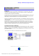
Aplex Operation
In normal operation the Aplex should be in the ‘Stand-by’ mode and acts as a ‘Data Gathering’
device for the Datalog system. The Datalog monitors all change of states of all inputs, and alarm
conditions are detected and handled by the Datalog computer system. If a Aplex zone input is
tampered or disconnected, this is presented as an alarm condition irrespective of the inhibit
condition. Tamper/Discon alarms can be ‘Reset’ in the normal way on the Datalog PC, but blue flags
will be displayed on the Main Site Plan as a reminder of un-cleared faults.
Many Aplex fault conditions are monitored, such as Battery Problem, Cabinet Tamper, Etc. The
Datalog will display such alarms as fault alarms. For Cabinet/Back tampers etc. the Datalog will
automatically silence the Aplex buzzer and clear the alert on the Aplex panel. With cable faults and
similar hardware errors, the Datalog will show the fault alarm as above but leave the Aplex alert
active so that an Engineer will have the information available on the Aplex display.
Whilst precise Aplex fault annunciation is provided by the Datalog, the recording of fault information
within the history database is limited to general fault type information and panel number etc. This is
because of the wide equipment platform with which the Datalog will operate and the vast quantity of
differing fault text descriptions.
The Datalog will also control Aplex CLEM outputs and offer automatic output switching during alarm
conditions or using Technical type inputs or by time of day/day of week. Custom software may also
be available to control outputs for special purposes.
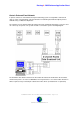
More than 1 Aplex panel can be connected to the Datalog using network drivers. If a network Aplex
system is in use then the zones of each Aplex are mapped sequentially into the Datalog alarm
system. (Note: for custom software applications, these numbers can vary)
Aplex panel 1 (Panel ID 1) = Zone 1 to 100
Aplex panel 2 (Panel ID 2) = Zone 101 to 200 etc.
Should the system grow, and more Aplex panels are required then Contact Cortech Developments to
increase the number of zones for the on site license and increase the number of active panels.
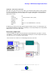
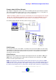
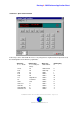
Panel Emulation
Clicking the Europlex button on the Main Screen or Menu Panel, or selecting Tools
!
Europlex from
the menus will display a mimic of an Aplex panel. This option allows checking and modification of an
Aplex Panel through the Datalog system without having to go to the panel. This option should only be
used by persons with knowledge of the operation of the Aplex panel and may need to consult the
Europlex manual for the codes required.
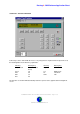
The panel simulation has a red led display and identified control keys. The display on the screen will
be identical to the display on the selected panel. A buzzer icon will flash to allow a visual indication
that the Aplex buzzer is active. By default the software will select the first panel that is on-line. If
there is more than one panel, the other panels can be selected by clicking the up/down buttons on
the Panel Address box. The detection of an alarm will automatically return the operator to the graphic
alarm management screen.