CreaseMaster Platinum - Reference Manual Table of Contents 1.0 1.1 1.2 1.3 General Operation Technical Data Safety Regulations Cautions Concerning Machine 2.0 2.1 2.2 Machine Assembly Power Supply Instructions Air Regulator Instructions 3.0 3.1 3.2 3.3 3.4 3.5 Getting Ready Paper Gate Adjustments Side Rail Set Up Air Nozzle Set Up Vacuum/Blower Adjustments Optional Conveyor Out Feed 4.0 4.1 Setting Up a Job Operating the Touch Screen 5.0 5.1 5.
1.1 TECHNICAL DATA Areas of Use: Paper Weight: Paper Formats: 12# - 18 point (45-385 gsm) Maximum 18”x 25.5” (45x57 cm) Minimum 3.5”x 5” (78.9cm x 12.7 cm) Electrical Configuration: Voltage: 108 – 127 VAC 5A at 50-60 Hz Operating Temp: Rated to be used up to 40 degrees C ambient 1.
Page 3
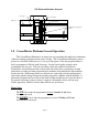
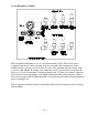
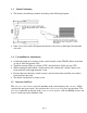
CM Platinum Machine Diagram Exit Tray Guide Laser/PhotoEye Magnetic Stop Paper Gate Assembly Registration Holes for aligning Op side Side Rail 1.0 CreaseMaster Platinum General Operation The CreaseMaster Platinum is an impact die score machine that effectively eliminates substrate cracking experienced with rotary scoring. The CreaseMaster Platinum is microprocessor controlled, making it easy to set up and program. It has the program ability to hold a maxiumum of 20 jobs with 10 creases.
2.0 Machine Assembly Remove and unpack all machine parts from the shipping carton. 2.1 Power Supply Instructions Before connecting the power cord to a wall receptacle, make certain the supply voltage is what the machine has been set up for. The voltage is marked on the sticker containing the serial number of the machine. If there are any discrepancies, please call your dealer first before plugging the machine in.
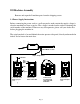
2.2 Air Regulator Assembly The CreaseMaster Platinum score dies are pneumatically driven. The air pressure is regulated from the air source (whether shop air or a stand-alone compressor) on the machine at the regulator/gauge/manifold assembly. The optimum pressure setting at the regulator is 60-100 psi. If scoring a job with many scores, you may need to increase the Impression Control to maintain a consistent impression.
Page 7
3.0 Getting Ready 3.1 Paper Gate Adjustments • With light to medium stock, the feed finger should be not adjusted down, as the front nozzles will hold the stack in position. Heavier and/or wider stock may require the feed finger to be lowered to the point that it will hold back the second sheet but allow the first sheet to pass. Feed Finger all the way up, and face lined up with beginning of slope on vacuum manifold 3.
3.3 Nozzle Positioning • The nozzles should be positioned according to the following diagram • Note: Very wide stock will require the nozzles to be closer to the Paper Gate than the side rails. 3.
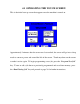
4.1 OPERATING THE TOUCH SCREEN This is the initial start up screen that appears once the machine is turned on. Approximately 2 minutes after the screen was last touched, the screen will go into a sleep mode to conserve power and extend the life of the screen. Touch anywhere on the screen to make it active again. To begin programming a new job, press the “Program New Job” key.
This screen appears after pressing the “ Program New Job ” key. This screen allows you the option of Batching. You are able to input the batch size, delay time between batches, and have the machine start automatically after each batch or start manually. You have the ability of turning the batch function “Off “ or “On” in this screen. *** During the Delay Time between batches the motor is still energized and the Handwheel is locked. You are not able to turn the Handwheel.
This screen appears after pressing the “ Next “ key. The number number “1” signifies the first crease you are going to program. Press the 0.00 key to enter the distance from the lead edge of the piece of paper to be creased to the position of the first crease. Touch the numbers that represent this distance. Use the Decimal (.) key to enter fractions of an inch/centimetre i.e. 5.5 Press the Back Space (BS) key to erase the last number entered if incorrect.
Pressing the Previous (PREV) key will return you back to the previous screen displayed. You will not lose information programmed into the crease positions unless you press the MAIN key where crease #1, #2,#3 � are displayed on the screen. Program any remaining creases in the same way you did previously.
After the 10th crease is programmed, pressing the NEXT key will advance you to the Strike Perf screen. Pressing the CREASE COMPLETE key will also advance you to the Strike Perf screen which is the next area requiring programming. Note: Strike Perf is an option that must be ordered from your dealer. It allows a perf line to be turned on and off on a page rather than running the length of the page. If your machine does not have the Strike Perf option, proceed to page 16 after pressing the OFF key.
This screen is the first one to be displayed should you want to use the pneumatic Strike Perf option OR if you want to continuously perf a page. If you want to continuously perf using a standard accessory holder, press the OFF key to advance to the next screen. To program the Strike Perf option, press the ON key and skip to page 19 of these instructions.
CONTINUOUS PERF USING STANDARD ACCESSORY HOLDER This screen does not affect continuous perf. Press the SKIP TEST PAGE key to advance to the next screen.
CONTINUOUS PERF USING STANDARD ACCESSORY HOLDER Press the RUN key to begin the job.
CONTINUOUS PERF USING STANDARD ACCESSORY HOLDER Press the RUN key to start the job running. Pressing the MAIN Key will return you to the initial programming screen. Press the CNTCLR key to zero the counter so that the system will count each sheet being perfed. If the machine times out while the job is running due to lack of paper in the feeder, simply press the RUN key to resume. Once the job is complete, press the MAIN key to return to the initial programming screen.
If you want to use the Strike Perf accessory holder to do continuous perfing, press the ContinuousPerf key.. If you want to program the Strike Perf option, press the STRIKE PERF key to move to the next programming screen. If you want the Strike Perf to start at the leading edge of the sheet press the YES button to advance to the next screen.
Press the 0.00 key to activate the keypad menu. Enter the length of the page and press the Enter key to proceed. Press the NEXT key to move to the next programming screen. The Strike Perf option can be programmed to come on and off up to 5 times for each piece of paper. Press the 0.00 key to program the position where you want the Strike Perf to begin. Once programmed, press the Enter key to return to the programming screen. Press the 0.
Perf is to turn off. You can repeat this sequence up to 5 times. If no more Strike Perf locations are needed, press the Next button key and proceed to the next screen. The Speed and Impression control keys do not effect the operation of the Strike Perf. Press RunTestPage to see the results of the programming. Press SkipTestPage if you want to move to the next screen without seeing a test page. NOTE: The pump must be turned on to feed paper properly.
Pressing PREV takes you back one screen to where you can select to run a test page or not. The Run and Save key allows you to program a name for the job you have just programmed. (See page 23) The Run key will start the job programmed without saving it for use at a later date. (See page 26) The Go to Edit Menu will allow you to reset the Batch, alter both the creases programmed and the Strike Perfs programmed before proceeding further.
Press the key to activate the keypad. The and keys scroll through the whole alphabet in upper and lower case and also give you access to numbers and some symbols. Once completed, press the Enter key to proceed. The screen will display the name you typed in. Touch the box with the name in it if you want to edit it. If not, press NEXT key to continue.
Once you have read this message, press NEXT to continue. The UP and DOWN keys referred to in the message are 2 screens forward from here. This screen displays job numbers and the name they were saved under. Use the UP and DOWN keys to change the program number displayed so that you can save in an empty job number or override the one you want to. Press SAVE key when you are in the spot you want to be.
Pressing the Run Now key advances you to the run menu. (See page 26) Pressing the Return to Main Menu key returns you to the initial Welcome screen. The job has been saved and can be recalled by pressing the Run Existing Job key on the Welcome screen.
The Run menu screen allows you to control certain aspects of how the job will run. The speed can be adjusted using the UP and DOWN keys to move the number displayed from 1-20, 20 is the fastest, 1 the slowest. Once it is known that the stock is running well, increase the speed as high as possible for maximum productivity. Slow the system down if jamming occurs due to curled stock or other factors. The impression strength can also be adjusted UP or DOWN from 1-6.
Press the UP or DOWN keys so that the job to be run is displayed. Press the OPEN SAVED JOB key to proceed. If the contents of the saved program are known and do not need editing, press the RUN AS DISPLAYED key to proceed. Return to page 18 for instructions on the Run Menu. If you want to review or edit the saved program, press the EDIT key and go to Page 11 for further instructions.
Other Screens: Safety Lid Must Be Closed For Machine to Run You Must Decrease Speed Of The Machine if Crease Is To Close To Lead Edge PLC Low Battery Warning Order Battery 1-800-265-3376 Page 28
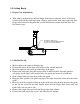
Idler Wheels/Perforating/Slitting 5.1 Idler Wheels The Idler Wheels (rubber tires on the accessory holders) are used to stabilize the stock as it passes over the boss wheel shaft, especially in the situation where a perf or slit are set up. They should be positioned 1-1½ in/2.6-4.4 cm from the edges of the paper with a minimum amount of contact pressure. Skewing of the stock can be adjusted slightly by increasing/decreasing pressure.
Perforating, and/or slitting can be performed with or without a score. As previously mentioned, if no scoring is desired, program ‘00’has been set aside for this task. The perforator blades are available with 2,4,6,8 and 12 teeth per inch as well as Microperf. The blades can be easily interchanged using the ring pliers supplied with the machine. Remove the accessory holder from the machine. Simply remove the retaining clip from the blade hub and pop off the blade.
through the machine square, you can feed a sheet into the machine using the hand wheel and align the lead edge of the sheet with a straight edge in the machine (such as the edge of the boss shaft). To adjust the squareness of feed, you can move the front or back of the operator side feed rail on the feed table to make sure the sheet travels through the machine squarely. If you adjust the operator side feed rail, you must adjust the nonoperator side rail as well.
6.0 Maintenance 6.1 Cleaning After each job, or halfway (approximately 24 hrs) through a very long job, it is recommended that the machine be blown off with compressed air to remove dust from the moving parts. Blanket wash may be used to remove ink from rollers/tires. Occasional application of a rubber roller rejuvenator will help keep the rollers/tires in good shape. The machine should have a thorough cleaning once a week. 6.
Page 33
Page 34
PARTS PART NO. Jr. 3K 6K 8K 8KP 12K FM FM CM 100 150 PRO FRIC PLUS (J-1) CM CM AIR DESCRIPTION FEED 10-001-GW X X X X X X Red, Preinked Pad w/holder 10-002-GW X X X X X X Black, Preinked Pad w/holder 10-003-GW X X X X X X Uninked pad w/holder 10-004-GW X X X X X X Felt Insert 10-005-GW X X X X X X Red Ink, 2 oz. bottle 10-006-GW X X X X X X Black Ink, 2 oz.
10-029-GW X X X X X X X X 10-030-GW X X X X X X X X X X Shaft Bushing w/Spring 10-031-GW X X X X X X X X X X Solid Bottom Roller X X X X X 10-033-GW X X X X X 10-033-OSL X X X X X 10-031-CM Feed Shaft Bushing w/Spring X 10-032-GW 10-032-DH Main Top Roller Main Platen Crash Pad OP Crash Pad GW 8000 PDS Main Platen Main Platen Deflector 10-033-CM X X X X Deflector Platen / Die 10-034-GW X X X X X Main Platen Grommets 10-035-GW X X X X
10-092-GW X X X X X X X X X X 4 TPI Perf. Blade 10-093-GW X X X X X X X X X X 6 TPI Perf. Blade 10-094-GW X X X X X X X X X X 8 TPI Perf. Blade 10-095-GW X X X X X X X X X X 12 TPI Perf. Blade 10-102-GW X X X X X X X X X X 16 TPI Perf.
20-002-GW X Register Lay Sheet 20-003-GW X Crash Pad 20-005-GW X Slot Plate w/Arm 20-007-GW X Forward/Back Adjustment Screw 20-008-GW X Head Height Adjustment Screw 20-010-GW X 20-015-GW X 20-016-GW X J-1 Wire Connecotr 25-004-GW X Circuit Enclosure 25-009-GW X Switch Plate/Circuit Mount 25-012-GW X Circuit Board- external impression control Footpedal w/Cord X X Speed / Impression Control Harness 30-009-GW X X X X X X X X X X 1/2" main structure shaft 30-011-GW
60-016-GW X X Conveyor Belt 60-017-GW X X Conveyor Belt Spool 60-020-GW X X Coveyor Top Roller O-Ring 70-003-GW X X Feeder Side Plate 70-006-GW X X Feed Platen 70-007-GW X X Feed Pulley w/spur gear 70-008-GW X X 1 ½” Feed Pulley X X 70-013-GW 70-013B-GW X X Ball Bearing Holder Mount Block X X X X Regulator Bracket 70-014-GW X X Steel Ball Bearing 70-015-GW X X Nylon Ball Bearing 70-019-GW X X O-Ring Drive Belt (Register Board) 80-007-GW X X Controller Boa
90-030-GW X X X X X 90-031-GW X X X X X 90-032-GW X X X X X Telephone Cable X X X X X Low Profile Tie Mounts 12V Cooling Fan 90-034-GW X Display Board Label 90-034S-GW X Operator Side Cover Strip 3k 90-054-GW X X X X X Print Head Mount Screws 90-055-GW X X X X X Print Head Rotation Screw 90-059-GW X X X X X 90-060-GW X X X X X 90-061-GW X X X X X 90-062-GW X X X X X X X X X X 110V Modular Switch w/fuseholder 90-062K-GW OP OP OP OP O
94-034-GW X X 94-034-8-GW X X X X 94-034-12-GW X Display Board Label (ALL MODELS SN 2111 AND HIGHER ) Operator Side Cover Strip 8K X Operator Siide Cover Strip 12k 94-072-GW X X Pneumatic Drive Unit 94-073-GW X X Complete Pneumatic Drive Unit w/Reverse #ring Head 94-083-GW X X LV Solenoid to MSTP Board Power Cable 94-084-GW X X Drive Unit Connection Metal Plate 96-009-GW X X Register Board 96-012-GW X X Register Guide 96-015-GW X X Register Board Ball Holder 96-017-G
CM-0003N X X X Bottom Die Narrow CM-0003LC X X X Bottom Die Combination Narrow / Wide CM-0003S X X X Botom Die Spring CM-0005 X X X Photo Sensor Cross Bracket CM-0006 X X X Spacer Block CM-0007 X X X End Support Block CM-0008 X X X Cylinder Mount Bracket CM-0009 X X X Cross Brace Bracket Support CM-0010 X X X Metal Display Panel CM-0030 X X Main Top Roller CM-0031 X X X Main Bottom Roller CM-0034 X X X Display Panel Label CM-0034S X X CreaseMaste
FLD-0099 FLD-0100 FLD-0108 X X X X X X Side Rail Ops Side X X Side Rail Non Ops Side X Display Board Springs FLD-0112 X X Pump Switch Plate FLD-0116 X X Magnetic Back Stop FLD-0117 X X Vacuum Belt FLD-0121 X X Paper Gate Support Shaft FLD-0124 X X Static Eliminator FLD-0126 X X Pump On/Off Switch FLD-0130 X X Vacuum Pump 110V FLD-0131 X X Vacuum Pump 220V FLD-0135 X X Hose Clamps FLD-0136 X X Snaploc Hose FLD-0137 X X Snaploc 90 Degree Elbow FLD-0138
RN028 X X X X X X unit numbering wheel retaining pawl RN029 X X X X X X 2x/4x action ratchet wheel retaining pawl RN030 X X X X X X 3x action ratchet wheel retaining pawl RN031 X X X X X X pawl mount shaft RN032 X X X X X X comb spring RN033 X X X X X X 2-piece comb spring (condensed head) RN034 X X X X X X comb spring mount screw RN035 X X X X X X knocken RN036 X X X X X X knocken mount screw RN044 X X X X X X repeat selector mo