PROSTAR P H O T O V O LTA I C S Y S T E M C O N T R O L L E R S OPERATOR’S MANUAL MODEL RATINGS PROSTAR-12 PROSTAR-20 PROSTAR-30 Rated PV current 12A 20A 30A Rated Load current 8A 16A 30A System voltage: 12 and 24 volts, auto selected ProStar models • Standard included in this • With LCD meter manual:
CONTENTS 1.0 2.0 3.0 4.0 5.0 6.0 GENERAL INFORMATION.................................................... 2 QUICK START INSTRUCTIONS ............................................ 3 INDICATORS ...................................................................... 4 3.1 LED Indicators .................................................. 4 3.2 Digital Meter & Disconnect .............................. 5 INSTALLATION INSTRUCTIONS ............................................ 6 4.1 Polarity Protection ............
• Even though the system is only 12 or 24 volts, both the PV array and battery can contain lethal amounts of electrical power. • Do not splash water on the controller, do not allow water to enter the ventilation slots. • Do not touch the heatsink. Under certain operating conditions, the heatsink can become hot. • Always install the controller in a vertical position. Ensure adequate space for ventilation, and never block the ventilation slots.
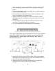
3. Connect the BATTERY first. Observe that all LED’s flash in sequence one time. 4. Connect battery SENSE leads (if utilized). This is recommended if the controller is placed more than 2 to 3 meters from the battery. 5. Connect the PV (solar array). With sunlight, the green CHARGING LED will light in 2 minutes. 6. Connect the LOAD. If the LED indicators begin to flash, the load is shorted. Refer to the detailed installation instructions. 7. The BATTERY TYPE at start-up is sealed (LED on).
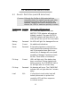
BATTERY CHARGE Green ON: Battery near full charge BATTERY CHARGE Yellow ON: Battery at middle capacity (about 35% to 80% SOC) NOTE: does not indicate a problem BATTERY CHARGE FLASH: Battery at low charge, warning ON: Load has been disconnected All LED’s Red SEQUENTIAL FLASH: Load is short-circuited High temperature shutdown High voltage disconnect Initial battery connection (startup) (flashes one cycle only) 3.
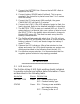
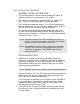
4.0 INSTALLATION INSTRUCTIONS 4.1 POLARITY PROTECTION (AND LED INDICATIONS) CAUTION: Although the ProStar is fully protected from reversed polarity, the system operator and other equipment may be at risk when polarities are reversed. Carefully check each connection and observe the LED’s to make sure polarity is correct. CONNECTION POLARITY RESULT AND LED INDICATION Battery Correct All 5 LED’s will sequence one time. BATTERY TYPE indicator will remain on (default is sealed).
4.2 INSTALLATION PROCEDURE GENERAL INSTALLATION NOTES: • The ProStar prevents reverse current leakage at night, so a blocking diode is not required in the system. • The ProStar is designed to regulate ONLY PV power. Do NOT connect to any other type of power generator. • The ProStar automatically selects 12 or 24 volt setpoints at battery connection. Do not connect a battery larger than 24 vdc (12 cells) or the controller will be damaged.
Multiple ProStar units can be paralleled at the system battery, but be careful that no PV sub-array exceeds a controller’s individual current rating. 3. BATTERY (+ and -) Before connecting the battery, check the open-circuit voltage of the system battery. It must be at least 8 volts for the controller to operate. If your PV system is 24 volts, the battery MUST be over 17 volts, or the controller will regulate at the 12 volt setpoints.
CHARGING indicator comes on after 2 minutes to confirm that the PV array has been properly connected. 6. LOAD (+ and -) Turn the load off. Connect the load to LOAD terminals, and then turn the load on. If the battery is below the load disconnect voltage, the load will be disconnected (normal LVD). There may be a short delay. If the load is short-circuited, the controller will instantly disconnect the load and flash the LED’s in sequence. If this occurs, remove the load and repair the short.
5.0 OPERATION 5.1 CONTROLLER OPERATION The ProStar is a fully automatic PV system controller that includes many electronic functions to protect both the controller and the PV system. Battery charging is managed by a constant-voltage, PWM algorithm that has been optimized for PV systems. The only manual tasks performed by the operator are: a. b. c. d. e. Installation (see section 4.0) Battery type selection (see section 4.2-7) Disconnect button (with LCD meter, see section 3.
Automatic Safety Disconnects • Load Short-Circuit: Instant load disconnect. The LED’s flash in sequence. Battery must be disconnected to clear and reset (see section 4.2-6) • High Temperature: At very high temperatures, PV array first disconnected, then the load. The LED’s flash in sequence. Auto reconnect as temperature falls. • Emergency: If battery is disconnected, the PV and load are instantly disconnected for safety and to protect the load.
6. Inspect for dirt, insects, nests, and corrosion. 7. Check that the controller functions and LED indicators are correct for the system conditions at that time. 5.4 TROUBLESHOOTING If something seems wrong with the PV system (for example, the load is not working or the battery is not charging), then it may be necessary to troubleshoot the controller. Some basic troubleshooting procedures are listed below. • • • • CAUTIONS: Troubleshooting should be attempted by qualified personnel only.
g. h. i. j. the battery. This will cause undercharging of the battery. See section 4.2-4. Check the condition of the battery. Determine if the battery voltage declines at night with no load. If unable to maintain its voltage, the battery may be failing. If all the ProStar LED’s are flashing in sequence, see item number 4 below. Check that the controller is operating at the correct system voltage (12 or 24 vdc), and that the battery has enough voltage (over 8 volts) to operate the controller.
d. If there is a problem with high voltage, the controller should go into the High Voltage Disconnect mode (see section 5.2). 3. LOAD NOT OPERATING PROPERLY a. Check that the load is turned on. Check that no system fuses are defective. Check that no system circuit breakers are tripped. Recall that there are no fuses or circuit breakers inside the ProStar. b. Check connections to the load, and other controller and battery connections. c. Check for proper LED indications on the ProStar.
6.0 TECHNICAL SPECIFICATIONS MODEL RATINGS PV current (amps) Load current (amps) ProStar-12 ProStar-20 ProStar-30 12 8 20 16 30 30 • All models both 12V and 24V (automatic selection) Note: Current ratings can be exceeded by 25% for up to 5 minutes. RELIABILITY MECHANICAL 5-year failure rates at a 90% confidence level • ProStar-12 .................................... < 0.1% • ProStar-20 .................................... < 0.1% • ProStar-30 .................................... 0.
P.O.