
User's Manual
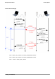
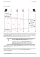
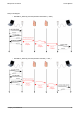
Table Of Contents
- 1. INTRODUCTION
- 2. RS232 SERIAL PROTOCOL PRESENTATION
- 3. setting internal waveport CF parameters
- 3.1 Configuring functional parameters
- 3.2 Wake-up and synchronization
- 3.3 Configuring control parameters
- 3.3.1 Selecting RF communication mode
- 3.3.2 Selecting radio channel when FHSS is deselected
- 3.3.3 Selecting radio board transmission power
- 3.3.4 Activating RSSI threshold auto-correction
- 3.3.5 Selecting the serial baud rate
- 3.3.6 Reading Waveport CF firmware version
- 3.3.7 Reading RSSI
- 3.3.8 RSSI command format
- 3.3.9 TEST Mode
- 4. SERVICE COMMANDS
- 5. COMMUNICATION MODES

Waveport CF user manuel Coronis Systems
Relay mode diagram:
When relay mode is used, the time-out (with respect to the transmitter) is not the same as with point-to-point
mode because of the additional time it takes to pass through intermediate nodes. The time-out specified by
RADIO_USER_TIMEOUT is still applied, but it does not take relays into account. The time-out value will be
applied by the last relay before the end-point receiver (R2 Delta = Radio_User_Timeout).
The value of RADIO_USER_TIMEOUT applied by the last repeater is
configured in the transmitter, not in the repeater itself.
In relay mode, repeaters use the RADIO_USER_TIMEOUT value
encapsulated in the transmitter's frame. Repeaters only uses its own
RADIO_USER_TIMEOUT setting when transmitting, not repeating.
In the above diagram, the value of RADIO_USER_TIMEOUT (set by the transmitter) corresponds to time
Delta R2 applied by Relay 2.
Delta 1 and Delta R1 are evaluated by the corresponding radio module, depending on the number of relays
(repeaters), the type of wake-up, duration, and the values of RADIO_USER_TIMEOUT and
RADIO_ACKNOWLEDGE.
Compact_Flash-UserManual 43