File : CS-SUP-MUTI-WTHERMAPP-E01.
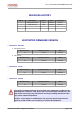
File : CS-SUP-MUTI-WTHERMAPP-E01.sxw REVISIONS HISTORY Rev. # Description Author Date Comments 1 Original document RCS 02/02/05 Version 1 2 Addon text FCC RCS 17/02/05 Version 2 SUPPORTED FIRMWARE VERSION ➢ WaveTherm - DALLAS European Version Manual version Firmware version Date V 01.04 15/10/04 Firmware version Date 1.0 V 81.05 15/10/04 Manual version Firmware version Date 1.0 V 01.02 15/10/04 Manual version Firmware version Date 1.0 V 01.00 15/10/04 1.
File : CS-SUP-MUTI-WTHERMAPP-E01.sxw TABLE OF CONTENTS 1 PRESENTATION........................................................................................................................... 6 2 REFERENCE DOCUMENTS......................................................................................................... 6 3 PRESENTATION OF THE WAVETHERM MODULES FUNCTIONALITIES................................ 7 3.1 SENSORS INTERFACE............................................................................
File : CS-SUP-MUTI-WTHERMAPP-E01.sxw 7 WAVETHERM MODULE FUNCTIONS ...................................................................................... 27 7.1 PARAMETER SETTING OF THE WAVETHERM MODULE...............................................................27 7.1.1 Reading of the module type..........................................................................................................27 7.1.2 Reading of the firmware version..................................................................
File : CS-SUP-MUTI-WTHERMAPP-E01.sxw 7.6.6 Configuration of the measurement period of the threshold detection...........................................59 7.6.7 Reading the threshold detection table..........................................................................................60 7.7 MANAGEMENT OF THE ALARM FRAMES........................................................................................61 7.7.1 Description of the parameters used.......................................................
File : CS-SUP-MUTI-WTHERMAPP-E01.sxw 1 PRESENTATION This document describes the functionalities of WaveTherm radio modules : WaveTherm – DALLAS WaveTherm – PT100 WaveTherm – PT1000 Used with DALLAS sensor Used with PT100 sensor Used with PT1000 sensor This document defines in an exhaustive way the applicatives data relating to serial dialog frames between a Wavecard and a host equipment , used to reach the data of the WaveTherm radio module.
File : CS-SUP-MUTI-WTHERMAPP-E01.sxw 3 PRESENTATION OF THE WAVETHERM MODULES FUNCTIONALITIES 3.1 SENSORS INTERFACE ➢ WaveTherm – DALLAS : The module is designed to manage to the maximum two DALLAS temperature sensors (type DS18B20). This DALLAS sensor of 1-wire type integrates a 12-bit internal converter. Each external sensor is connected to the module by a cable equipped with a BINDER connector of 3-pin type.
File : CS-SUP-MUTI-WTHERMAPP-E01.sxw 3.2 READ TEMPERATURES The WaveTherm module has the following possibilities: To read the current temperature ; To transmit the last N temperatures stored, in one frame. If two temperature sensors are used, then the WaveTherm return the last N/2 values of each sensor. • WaveTherm – DALLAS : N = 48 temperatures • WaveTherm – PT100 : N = 24 temperatures • WaveTherm – PT1000 : N = 24 temperatures 3.
File : CS-SUP-MUTI-WTHERMAPP-E01.sxw 3.4 MANAGEMENT OF THRESHOLD ALARMS The WaveTherm module detects when the values exceed the threshold levels (high or low) for a given period of time. The WaveTherm – PT100 and PT1000 may be configured with a precision level offering a more reliable measurement even in environments with excessive interference (see chapter 7.2.1).
File : CS-SUP-MUTI-WTHERMAPP-E01.sxw 3.5 STORAGE OF CALIBRATION PARAMETERS The WaveTherm module manage a non-volatile memory area accessible by radio command, and allowing to store up to 32 bytes. This area is not used by the internal process, and is generally used to store the parameters relative to the calibration of the module, and can be read, or modified by specifying the start address, and the size of the data. 3.
File : CS-SUP-MUTI-WTHERMAPP-E01.sxw 3.8 SENSOR FAULT DETECTION (if supported by the module) For all modules, temperature probe absence or error detection is carried out during a write request and is indicated by the presence of a specific value which does not correspond to a possible temperature value.
File : CS-SUP-MUTI-WTHERMAPP-E01.sxw 4 DATA EXCHANGE PRINCIPLE WITH A WAVETHERM MODULE The WaveTherm module uses the WAVENIS protocol. The choice of mode used is initiated by the read element which uses a different set of commands (see WaveCard document) when sending commands to the WaveCard. The following chart indicates the read modes possible as well as their typical applications.
File : CS-SUP-MUTI-WTHERMAPP-E01.sxw ➢ Example in Point-to-point mode : Remark : Generally, the exchanges examples given in this document will be in Point-to-point mode, except when the context depends directly on the mode of exchanges. This type of radio exchange allows to send a request, then to await a response of the remote equipment.
File : CS-SUP-MUTI-WTHERMAPP-E01.sxw The data field of each command must be formatted according to the following table : DATA CMD 6 bytes variable ( max : 152 bytes) 0x20 Radio address from equipment to reach Data to transmit 0x30 Radio address from transmitter equipment Received Data the first byte of the field 'data to transmit' (or 'Received Data') contains an applicative command (or its acknowledgement).
File : CS-SUP-MUTI-WTHERMAPP-E01.sxw 5 INFORMATION RELATIVE TO THE PROBES ASSOCIATED WITH THE WAVETHERM MODULES 5.1 DALLAS Probes 5.1.1 Coding of temperatures for the DALLAS probe type DS18B20 These probes have a resolution of 12 bits and their value is coded on two bytes (MSB first) Negative values are expressed in two's complements with addition of a sign.
File : CS-SUP-MUTI-WTHERMAPP-E01.sxw 5.1.3 Setting of the probe coefficient parameters The precision of DALLAS probes is indicated by the manufacturer as ±0.5°C (-10°C to +85°C) and requires no calibration before use. However, it is possible to improve this precision if the user wishes to calibrate the probe. In this case, the WaveTherm module contains a 32-byte memory zone for storage of transfer coefficients after calibration.
File : CS-SUP-MUTI-WTHERMAPP-E01.sxw 5.2 PT100 and PT1000 probes 5.2.1 Representation of temperature values Due to the high level of precision required of the temperature values processed by the module, WaveTherm PT100 or PT1000 are true numbers (with a mantissa and exponent). They are represented in the form of a 32-bit floating number. The format used is the standard IEEE format with precision coded on 32 bits (+/-5.
File : CS-SUP-MUTI-WTHERMAPP-E01.sxw 5.2.2 Calibration of radio module ➢ Factory calibration The precision of PT100 and PT1000 probes is such that the WaveTherm module measurement chain requires calibration. This calibration is carried out automatically in the factory and the product is supplied ready for use. ➢ Re-calibration on site Re-calibration on site is possible under certain conditions. To carry out this operation, it will be necessary to connect two calibration precision resistances.
File : CS-SUP-MUTI-WTHERMAPP-E01.sxw contents of RECEIVED_FRAME response Data Field (max : 152 bytes) Acknowledgement of the applicative command Status de l'étalonnage Reference resistance A (LSB First) Reference resistance B (LSB First) 1 byte 1 byte 4 bytes 4 bytes 0x88 0x00 : calibration OK 0xFF : calibration error Resistances A and B are restored in the 32-bits floating numbers format (LSB first). Format described in chapter 5.2. 5.2.
File : CS-SUP-MUTI-WTHERMAPP-E01.sxw All coefficients are regarded by the radio module as a single parameter. Parameters Description 0x32 Coefficients of probe 1 0x33 Coefficients of probe 2 Each parameter is composed of 8 coefficients of 32 bits (floating IEEE) with a total size of 32 bytes.
File : CS-SUP-MUTI-WTHERMAPP-E01.sxw 6 MODIFICATION OF THE INTERNAL PARAMETERS 6.1 INTERNAL PARAMETERS LIST ACCESSIBLE BY RADIO COMMANDS 6.1.1 Parameters common to all WAVETHERM versions The table below describes the internal parameters accessible by standard read and write commands. N° Description Size (in bytes) Access right Default value Hexa. Decimal Depending of the module used (see 6.1.
File : CS-SUP-MUTI-WTHERMAPP-E01.sxw 6.1.2 Parameters specific to the WaveTherm – DALLAS module N° Description Default value Size (in bytes) Access right Hexa.
File : CS-SUP-MUTI-WTHERMAPP-E01.sxw 6.1.4 Parameters specific to theWaveTherm – PT1000 module N° Description Default value Size (in bytes) Access right Hexa.
File : CS-SUP-MUTI-WTHERMAPP-E01.sxw 6.1.
File : CS-SUP-MUTI-WTHERMAPP-E01.sxw 6.2 PRINCIPLE OF READING AND WRITING OF INTERNAL PARAMETERS Document [DR1] details the exchanges modes, and their associated requests; with an aim of sending data to a distant module. This chapter details the data field in order to configure the internal parameters of the WaveTherm modules.
File : CS-SUP-MUTI-WTHERMAPP-E01.sxw ➢ Format of access for parameter (s) writing Contents of request REQ_SEND_FRAME Data field (max : 152 bytes) Applicative command Number of parameters read Number of the 1st parameter Size of the 1st parameter Data of the 1st parameter ... 1 byte 1 byte 1 byte 1 byte variable ...
File : CS-SUP-MUTI-WTHERMAPP-E01.sxw 7 WAVETHERM MODULE FUNCTIONS 7.1 Parameter setting of the WaveTherm module some of the parameters of module information are accessible by standard internal parameters read and write commands, described in chapter 6.2; whereas other parameters of information are accessible by specific applicative commands. 7.1.1 Reading of the module type The module type is obtained by interrogating the WaveTherm module, with the GET_TYPE command.
File : CS-SUP-MUTI-WTHERMAPP-E01.sxw 7.1.2 Reading of the firmware version The firmware version of the module is obtained by interrogating the distant module with GET_FIRMWARE_VERSION command.
File : CS-SUP-MUTI-WTHERMAPP-E01.sxw 7.1.3 Reading of the date and time of the module Applicative command Description 0x12 Request to read the date and time of the module 0x92 Response to request to read the date and time of the module Remark : In the command byte coding, the Response frame type are taking the Request command byte value with the MSB bit set to 1.
File : CS-SUP-MUTI-WTHERMAPP-E01.sxw 7.1.4 Setting the date and time of the module Applicative command Description 0x13 Request to set the date and time of the module 0x93 Response to request to set the date and time of the module Remark : In the command byte coding, the Response frame type are taking the Request command byte value with the MSB bit set to 1.
File : CS-SUP-MUTI-WTHERMAPP-E01.sxw 7.1.5 Access to the user data area The WaveTherm module manage a non-volatile memory area accessible by radio command, and allowing to store up to 32 bytes. This area is generally used to store the parameters relative to the calibration of the module, and can be read, or modified by specifying the start address, and the size of the data.
File : CS-SUP-MUTI-WTHERMAPP-E01.sxw ➢ Access in Writing The user has to specify the address of the first byte to be written, the total number of bytes to be written, and then the data.
File : CS-SUP-MUTI-WTHERMAPP-E01.sxw 7.1.6 Initialization of the sensors The initialization command returns the number of sensors detected. Remark : For the WaveTherm – DALLAS only, when the sensors are detected, the module returns their identifier.
File : CS-SUP-MUTI-WTHERMAPP-E01.sxw 7.2 READING THE CURRENT VALUE OF THE TEMPERATURE SENSORS The WaveTherm module has the possibility to read the current temperature when the sensors are wired, and initialized. If not the input relative to the sensor not wired (or initialized) returns the following values : WaveTherm – DALLAS : 0x4FFF WaveTherm – PT100 : 0xFFFFFFFF WaveTherm – PT1000 : 0xFFFFFFFF In addition, this command returns the Operating Mode, and Application Status bytes. 7.2.
File : CS-SUP-MUTI-WTHERMAPP-E01.sxw Contents of request REQ_SEND_FRAME Data Field (max : 152 bytes) Applicative Command Precision level 1 byte 1 byte 0x01 (*) (*) The precision field is used only for the modules : - WaveTherm – PT100 - WaveTherm – PT1000 The WaveTherm – DALLAS doesn't support the precision capability. In this case the precision field doesn't exist (size = 0 byte).
File : CS-SUP-MUTI-WTHERMAPP-E01.sxw 7.2.3 Reading the current ohmic values of the sensors Compatibility : - WaveTherm – PT100 - WaveTherm – PT1000 When using WaveTherm – PT100, or PT100 modules, it is possible to read the current ohmic value of the sensors. This type of reading may be started with one of several precision levels (0 to 3). In general, precision level 0 is sufficient. The other precision levels are used in difficult environments (refer to chapter 7.2.1).
File : CS-SUP-MUTI-WTHERMAPP-E01.sxw 7.3 WAKE-UP SYSTEM MANAGEMENT In order to reduce module power consumption, a wake-up period parameter setting system is incorporated.
File : CS-SUP-MUTI-WTHERMAPP-E01.sxw 7.3.3 Set a new wake-up period The WaveTherm module wake-up default setting is every second. The wake-up period may be easily modified by entering a new value in the 'default wake-up period parameter'. Attention, the value associated with this parameter may not exceed 10 seconds. Attention, an erroneous value of this parameter involves a wake-up every second, the maximum value is 0x0A (10 seconds). 7.3.
File : CS-SUP-MUTI-WTHERMAPP-E01.sxw The time windows function as follows, Set the start time for the first time window and its wake-up period ; Set the start time for the second time window and its wake-up period ; Select the days of the week during which the time windows are enabled ; 'Enable time windows by day of the week' = 0x7F Validate the time window mode with the 'wake-up system status word'.
File : CS-SUP-MUTI-WTHERMAPP-E01.sxw 7.3.6 Set the day/night system parameters according to day of the week The day/night system according to the day of the week parameter setting procedure is the same as that described in the previous chapter with the exception that the “Enable time window according to the day of the week” parameter is only set for days required. For example, we wish to enable the time window from Monday to Wednesday.
File : CS-SUP-MUTI-WTHERMAPP-E01.sxw 7.4 PARAMETER SETTING OF THE DATALOGGING MODE The Datalogging mode enables periodic logging of temperatures at each input (by selecting the precision index for PT100 and PT1000 probes). The frequency of these readings may be set in three modes: index logging in time steps index logging once a week index logging once a month When the storage table is full, the most recent measurements crush the oldest values , this mode is called permanent loop.
File : CS-SUP-MUTI-WTHERMAPP-E01.sxw The precision levels may be described as follows, Precision = 0x00 : normal precision (fastest measurement) Precision = 0x01 : high precision Precision = 0x02 : very high precision Precision = 0x03 : maximum precision (slowest measurement) Remark: Above all, the primary function is to preserve measurement precision, even in an environment with considerable interference, and not to improve the measurement precision of the probe itself.
File : CS-SUP-MUTI-WTHERMAPP-E01.sxw 7.4.4 Index logging in time steps This type of datalogging is used to log the index value for each input at periods ranging from one minute to over thirty hours. The time of the first logging may be set with a parameter. When the datalogging mode in time steps is enabled, the system only logs the memorised index values as soon as the preset time is attained; and this until the datalogging mode is disabled.
File : CS-SUP-MUTI-WTHERMAPP-E01.sxw 7.4.5 Index logging once a week This type of datalogging is used to log the index value for each input once a week. The time and day of the week logging is carried out may be set with a parameter.
File : CS-SUP-MUTI-WTHERMAPP-E01.sxw 7.4.6 Index logging once a month This type of datalogging is used to log the index value for each input once a month. The time and day (from 1 to 28) logging is carried out may be set with a parameter.
File : CS-SUP-MUTI-WTHERMAPP-E01.sxw 7.4.7 Reading the logged temperature values Standard datalogging allows a periodic collection of temperature measurements up to N temperatures. If two temperature sensors are used, then the WaveTherm return the last N/2 values of each sensor. It functions in 'permanent loop' mode, i.e. the most recent measurements replace the oldest measurements. WaveTherm – DALLAS : N = 48 temperatures; N = 24 temperatures; N = 24 temperatures.
File : CS-SUP-MUTI-WTHERMAPP-E01.sxw ➢ WaveTherm – DALLAS : The maximal number of logged values is 48 if only one sensor is activated, and 24 when two sensors are activated. The storage table is defined as follow : Number of activated sensor 1 Number of values per sensor 48 temperatures from sensor A 24 temperatures from sensor A 2 24 temperatures from sensor B Structure of the storage table Size Description 2 bytes Temperature A (instant t) 2 bytes Temperature A (instant t – 1T) ...
File : CS-SUP-MUTI-WTHERMAPP-E01.sxw 7.5 ADVANCED DATALOGGING When the WaveTherm support the Advanced Datalogging, the datalogging allows a periodic collection of temperature measurements up to M temperatures. If two temperature sensors are used, then the WaveTherm return the last M/2 values of each sensor. WaveTherm – DALLAS : WaveTherm – PT100 : WaveTherm – PT1000 : M = 4500 temperatures; M = 2000 temperatures; M = 2000 temperatures.
File : CS-SUP-MUTI-WTHERMAPP-E01.sxw 7.5.2 Parameter setting of the Advanced Datalogging mode To activate the advanced datalogging, the user have to follow the following steps : Configure the index logging in time steps (see chapter 7.4.4); Choose the measurement period; Select the start time of the first measurement ; Select the precision level (only for the PT100, PT1000 sensors).
File : CS-SUP-MUTI-WTHERMAPP-E01.sxw Start Step 1 Reading the number of logged values (parameter 0x0B) Step 2 Reading of the totality, or a part of the storage table Step 3 Number of measurements >M Step 4 Re-initialization of the storage table End Remark : The step 3 could be suppressed. Indeed, after reading the totality of the storage table, the user can systematically re-initialize the storage table.
File : CS-SUP-MUTI-WTHERMAPP-E01.sxw ➢ Reading the number of logged values WaveTherm modules supporting the Advanced Datalogging has the possibility to store up to M temperature values. If one sensor is wired, up to M values are affected to this sensor, if two sensors are wired, up to M/2 values are affected to each sensor.
File : CS-SUP-MUTI-WTHERMAPP-E01.sxw ➢ In case of error If the numbers of the requested recordings doesn't exist, then the response frame will have the following format : Contents of the response RECEIVED_FRAME Data Field (max : 152 bytes) Applicative Command Frame number 1 byte 2 bytets 0x86 0xFF : Error Attention, if the number of requested recordings is higher than the number of available recordings, then : - The WaveTherm – DALLAS returns the error frame.
File : CS-SUP-MUTI-WTHERMAPP-E01.sxw (*) Data relative to the recordings : The format of this field varies according to the type of WaveTherm used. ➢ WaveTherm – DALLAS : Data relative to the recordings Number of the first recording returned (MSB First) Number of the last recording returned (MSB First) Temperature of the sensor Temperature of the sensor Temperature of the sensor 2 bytes 2 bytes 2 bytes 2 bytes 2 bytes ...
File : CS-SUP-MUTI-WTHERMAPP-E01.sxw 7.5.5 Structure of the data when two sensors are activated When two sensors are wired to the module, the numbering of the recordings is processed as follow : Number of the recordings, from Description the most recent to the oldest n Most recent recording of the input 2, at instant t n-1 Most recent recording of the input 1, at instant t ... ...
File : CS-SUP-MUTI-WTHERMAPP-E01.sxw 7.5.6 Usage limit of the multi-frame mode The Wavenis protocol doesn't allow the usage of the multi-frame mode in repeater mode, i.e. When the module is reach through relaying equipments. It is up to the interrogator equipment to format the frames so that the response fit in a single frame.
File : CS-SUP-MUTI-WTHERMAPP-E01.sxw 7.6 MANAGEMENT OF THRESHOLD ALARMS The WaveTherm module may be configured to detect when the values exceed threshold levels (high or low). Three types of threshold alarm detection methods may be programmed : immediate threshold alarm detection threshold alarm detection for a given continuous period of time (successive mode) threshold alarm detection for a total period of time (cumulative mode) 7.6.
File : CS-SUP-MUTI-WTHERMAPP-E01.sxw 7.6.2 Precision level of the measurement Compatibility : - WaveTherm – PT100 - WaveTherm – PT1000 Temperature measurement may be started with one of several precision levels (0 to 3). In general, precision level 0 is sufficient. The other precision levels are used in difficult environments. The aim of these precision levels is to compensate for measurement errors induced by the 50 Hz frequency.
File : CS-SUP-MUTI-WTHERMAPP-E01.sxw 7.6.4 Principle of the detection modes ➢ In cumulative mode, an alarm is detected when the total temperature threshold alarm time is higher than the set duration parameter.
File : CS-SUP-MUTI-WTHERMAPP-E01.sxw 7.6.5 Selection of the threshold detection modes, and activation of the detection The threshold detection modes are selected by positionning the bit b6 of the Operating Mode byte. By default, the successive mode is selected. The threshold detection is activated by positioning the bit b4, or b5 of the Operating Mode byte.
File : CS-SUP-MUTI-WTHERMAPP-E01.sxw 7.6.7 Reading the threshold detection table The module store in an internal table the information relative to the detection of a threshold alarm. This table can store up to 5 events relative to high threshold detection, and up to 5 events relative to Low Threshold detection.
File : CS-SUP-MUTI-WTHERMAPP-E01.sxw 7.7 MANAGEMENT OF THE ALARM FRAMES The WaveTherm module offers the possibility to automatically transmit radio frames when an occurrence is detected. The following occurrences may provoke an automatic alarm: High threshold detection; Low threshold detection; End of battery life detection; Probe fault detection (only with WaveTherm – PT100, and WaveTherm – PT1000 modules).
File : CS-SUP-MUTI-WTHERMAPP-E01.sxw 7.7.
File : CS-SUP-MUTI-WTHERMAPP-E01.sxw 7.7.4 Triggering an alarm frame After detection of a fault, if the configuration mode authorises transmission of alarms, the module transmits an alarm frame (applicative command 0x40).
File : CS-SUP-MUTI-WTHERMAPP-E01.sxw 7.8 END OF BATTERY LIFE DETECTION To detect the end of battery life, the WaveTherm module uses the power metering principle rather than measurement of the battery voltage. Lithium batteries are, in particular during passivation, unsuitable for the voltage measurement method to determine the remaining capacity. The WaveTherm records and evaluates all events (measurements, transmissions) to decrement the power meter according to the battery used.
File : CS-SUP-MUTI-WTHERMAPP-E01.