RTM Elster AMCO applicative PFS Coronis Systems EVO RTM Applicative Reference Guide Users Manual EVO RTM-UserMan 1
RTM Elster AMCO applicative PFS Coronis Systems Coronis Systems RTM Elster AMCO Products, EVO RTM-UserMan 2
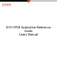
RTM Elster AMCO applicative PFS Coronis Systems Revision History Rev.
RTM Elster AMCO applicative PFS Rev. 15 Description Updated document Coronis Systems Author AMR Date 26 Jul 2007 Comments Corrections added : - §4.1: Data max length correction (173 instead of 174), - §4.2.2: comments added when writing only operating mode, - §5.4.6: error corrected in Encoder Unit LSB Byte description, - §5.4.7: details on encoder data returned - §5.
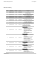
RTM Elster AMCO applicative PFS Coronis Systems DOCUMENT CONTROL AND APPROVAL Document Name Revision Author Date EVO RTM-UserMan 17 Adam Molnar 18 October 2007 Name Title Company Bruce A.
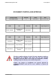
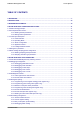
RTM Elster AMCO applicative PFS Coronis Systems TABLE OF CONTENTS 1.DEFINITIONS...................................................................................................................................................7 2.INTRODUCTION............................................................................................................................................10 3.REFERENCE DOCUMENTS........................................................................................................
RTM Elster AMCO applicative PFS Coronis Systems 5.5.5.Time Of Use (TOU) buckets configuration and readings...............................................................43 5.6.Automatic Radio transmission (pseudo bubble up mode - Fixed Network Only)...........................45 5.6.1.Pseudo bubble up parameters list..................................................................................................45 5.6.2.Pseudo bubble up allowed commands list................................................
RTM Elster AMCO applicative PFS Coronis Systems 1.Definitions Absolute Encoder: A meter register, that when queried by the Radio Transmitter module, will reply back to the Radio Transmitter module with the exact reading of the register odometer reading. Automatic Frequency Control: AFC guarantees top performance over the full lifetime of devices, keeping Rx carrier frequencies aligned to Tx.
RTM Elster AMCO applicative PFS Coronis Systems Quality of Service (QoS): Quality of Service (QoS) is an empirical, relative gauge of communications in a network derived by an algorithm which is balanced to minimize RF communications while finding the best communications path. Quality of Service is determined by a “balance” of 4 parameters: Device Class (application dependent: sensor, valve, actuator, gateway…), Remaining energy (no limit if powered by mains), RSSI, Number of “attached” children.
RTM Elster AMCO applicative PFS Coronis Systems RTC - Real Time Clock RTM – Radio Transceiver Module SDP - Service Discovery Protocol TOU – Time of Use ULP - Ultra-Low-Power WBX – Wavebox (Collector) WF – Waveflow (Radio Transmitter module) WNM – Wavenet Manager EVO RTM-UserMan 10
RTM Elster AMCO applicative PFS Coronis Systems 2.Introduction This document specifies all the features embedded in the RTM Elster AMCO radio module. A part of these features are compatible with Coronis Standard RTM. Functionalities added specifically for Elster AMCO are based on last “Statement of Conformance” document provided to CORONIS listed below : – – – “Coronis Conformance Doc - Fixed - 09.28.06 AMCO v11_revised_by_AMCO.xls”, “Coronis Conformance Doc - Walk-by 10.2.06 v4 revised by AMCO.
RTM Elster AMCO applicative PFS Coronis Systems 4.RTM Elster AMCO Configuration access RTM Elster AMCO as several embedded features, each one detailed later in this document, that are fully configurable using radio frames. This section describes radio frame generic format and explains how to access to the configuration of each embedded feature. 4.1.
RTM Elster AMCO applicative PFS Coronis Systems Note : point-to-point exchange commands have the following format: (all exchanges modes are described in document DR[7]) CMD NAME DESCRIPTION 0x20 REQ_SEND_FRAME Request to send a radio frame with the waiting for the radio response. 0x30 RECEIVED_FRAME Received radio frame by the radio board.
RTM Elster AMCO applicative PFS Coronis Systems 4.2.Internal parameters access This chapter details the applicative data field used for reading or writing RTM Elster AMCO internal parameters. The complete list of accessible parameters is described in Appendix A at the end of this document.
RTM Elster AMCO applicative PFS Coronis Systems 4.2.2.Writing internal parameters Writing request data format Operating Applicative Mode command (1) Mask on Operating mode (indicate the bits that must be updated) (1) Number of param to write (2) 1st param ID 1st param size 1st param new value 2 bytes 1 byte 1 byte 1 byte variable 2 bytes 0x19 ... nth param ID nth param size nth param new value ...
RTM Elster AMCO applicative PFS Coronis Systems Writing acknowledgment data format in case of frame format error Applicative acknowledgment command Operating Mode Status of writing 1 byte 2 bytes 1 byte 0x99 Operating Mode current value 0x00 --> update Operating Mode OK 0xFF --> Syntax error (not enough bytes in the request) 4.3.Control bytes description Some internal parameters are very useful to configure RTM Elster AMCO module and verify its state.
RTM Elster AMCO applicative PFS Coronis Systems 4.3.2.Operating Mode The “Operating Mode” is used to activate/deactivate each RTM Elster AMCO feature. This parameter is accessible through the command write parameters (described in section 4.2.2). “Operating Mode” parameter is systematically returned in generic header present in almost each response frame of the RTM Elster AMCO.
RTM Elster AMCO applicative PFS Coronis Systems 4.3.3. Alarm Configuration “Alarm Configuration” parameter is used to enable automatically alarm transmission on fault or other anomaly independently. Some internals features can be associated to an alarm configuration bit. To be sure that the Alarm frame will be sent after fault or problem detection, the user must take care that the corresponding “Operating Mode” bit is correctly set.
RTM Elster AMCO applicative PFS Coronis Systems 4.3.4.Application Status “ Application Status” parameter give at any time RTM Elster AMCO fault, or consumption-rate, status. Each RTM Elster AMCO internal feature that can be activated or deactivated through its corresponding bit in “Operating Mode” has an associated status bit in “Application status” parameter. User has to reset each bit by writing the “Application Status” parameter once the default has been handled.
RTM Elster AMCO applicative PFS Coronis Systems 4.3.5.Leakage Detection Status This control byte is used to detect leakage in real time. Indeed, each bit is set to one when a leakage is detected and reset to zero automatically when it ended. This information can be read by the standard read parameter command. This parameter is in read access only.
RTM Elster AMCO applicative PFS Coronis Systems 4.4.Writing RTC parameter RTM Elster AMCO RTC can be updated using “Write Parameter” command.
RTM Elster AMCO applicative PFS Coronis Systems 4.5.Meter reading sampling period configuration Several RTM Elster AMCO embedded features (datalogging in time steps, leakage detection, back flow detection) are based on periodic reading management. So, in order to synchronize these features RTM Elster AMCO offers the possibility to program a kind of “Meter Reading Sampling Period” principle that is shared between the features listed above in parenthesis. 4.5.1.
RTM Elster AMCO applicative PFS Coronis Systems 5.RTM Elster AMCO functionalities 5.1.Fixed Network/Walk By/ Drive By switching method (Refers to DR[5] Section 1.0.1) According to §4.3.2 (Operating mode parameter description), RTM Elster AMCO is able to operate in “Fixed” network, “Walk By”, and “Drive By” installations. The operation in “Walk By” and “Drive By” is exactly the same.
RTM Elster AMCO applicative PFS Coronis Systems Datalogging table structure for two Ports (A & B) connected: RTC value on last logged readings on each Port Last logged reading on Port A Log 0 7 bytes 4 bytes ... Port A Log (m-2) Port A Log (m-1) Last logged reading on Port B Log 0 4 bytes 4 bytes ... Port B Log (m-2) Port B Log (m-1) 4 bytes 4 bytes 2100 logged readings maximum whatever the number of Ports connected m= 1050 readings max.
RTM Elster AMCO applicative PFS Coronis Systems 5.2.2.Datalogging mode activation Datalogging mode is activated (or deactivated) by setting bits 3 and 4 in “Operating Mode” parameter. ATTENTION : Stopping then restarting the datalogging mode implies the re-initialization of the storage table. In this case, all the logged readings will be lost. It is advised to configure and activate the datalogging at the same time (with a single radio frame).
RTM Elster AMCO applicative PFS Coronis Systems 5.2.5.Datalogging once a month This type of datalogging is used to log the readings for each Port once a month. The time and day (from 1 to 28) logging is carried out may be set with a parameter. Parameters : Time of measurement (datalogging once a month) : this parameter allows to synchronize the periodic measurement. It is expressed in multiple of hour, and its value must set from 0 to 23.
RTM Elster AMCO applicative PFS Coronis Systems 5.3.RTM-Register interface (Refers to DR[3] Section 1.0.17 to 1.0.19; DR[4,5] Section 1.0.16 and 1.0.17) RTM Elster AMCO radio module is able to manage up to four Ports connected to pulse registers or up to two Ports connected to encoders. Register interface selection (pulse or encoder) is made by parameter configuration. So, there is only one embedded software reference to manage.
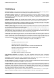
RTM Elster AMCO applicative PFS Coronis Systems 5.3.2.Encoder three wire interface Data +v 0v +v Data 0v PORT B PORT A RTM Elster AMCO encoder Interface Encoder compatibility list : RTM Elster AMCO first release is compatible with the encoders below : Elster AMCO Scancoder – Specs : 6170 M 1009 Elster AMCO Invision 11Class – Specs : 6170 m 1042 Elster AMCO Invision 21Class – Specs : 6170 Q 0009 SENSUS ECR II and III encoders: – Specs : ui1203r19.
RTM Elster AMCO applicative PFS Coronis Systems RTM Elster AMCO encoder profile list : RTM – Single or Dual Port(s) : Ports A & B are used for encoders reading. Note: Since wiring connections on PCB are different between pulse and encoder RTM, the profile configuration has to be made by Coronis during manufacturing stage.
RTM Elster AMCO applicative PFS Coronis Systems 5.4.RTM-register pairing 5.4.1.Programming current register reading (pulse register only) This feature allows to initialize the current reading of each Port. RTM Elster AMCO measures, and count pulses coming from the pulse register. It is thus necessary to establish the link between the reading of the meter given in volume unit (gallon, for example), and RTM Elster AMCO current reading accessible through radio link.
RTM Elster AMCO applicative PFS Coronis Systems 5.4.2.Programming pulse value (pulse register only) In order to know through a radio command the pulse value of the meter connected to the RTM Elster AMCO, specific parameters for each Port allows to store the corresponding pulse value. The pulse value is used to convert the water consumption read in number of pulses, in volume unit ( gallon for example). RTM Elster AMCO provides up to 4 parameters to store the pulse value of each wired water meter.
RTM Elster AMCO applicative PFS Coronis Systems The table below gives the different possible unit: Unit used (hexadecimal) [b7:b4] Unit 0 liters 1 kilo-liters 2 US gallons 3 US gallons x 1000 4 Imperial gallons 5 cubic feet x 100 6 cubic meters 7 cubic meters x10 8 cubic meters x 100 9 to F Reserved for future use 5.4.4.Programming meter model (pulse register only) “meter model” parameters gives an indication on the digital register type connected on each Port.
RTM Elster AMCO applicative PFS Coronis Systems The table below gives the correspondence between the meter type parameter value and the physical digital register connected: Meter type value Corresponding Meter model 0x00 Unknown (default) 0x01 TBD by Elster AMCO (ex : C700 5/8”) 0x02 TBD by Elster AMCO (ex : C700 1”) 0x03 TBD by Elster AMCO (ex : C700 1.
RTM Elster AMCO applicative PFS Coronis Systems 5.4.5.Encoder model detection (Refers to DR[3] Section 1.0.17; DR[4,5] Section 1.0.16) RTM Elster AMCO embeds a feature allowing to recognize the encoder model connected. This feature is performed either when profile selection parameter is programmed with encoder profile value, or using a dedicated radio command. RTM Elster AMCO run all encoders drivers and recognizes the connected encoders models.
RTM Elster AMCO applicative PFS Coronis Systems Encoder model is then stored in an internal parameter which is in read access only. Applicative command Associated internal parameters Description 0x18 0x1D ; 0x1E Request to read the encoder model parameters 0x98 0x1D ; 0x1E Encoder model reading response “encoder model” parameters are accessible by standard reading parameters command (described in §4.2.). 0x1D encoder model on Port A, 0x1E encoder model on Port B, 5.4.6.
RTM Elster AMCO applicative PFS Coronis Systems 5.4.7.Reading encoder internal data (Encoder only) This feature allows to access directly to the information returned by the encoder(s) connected to RTM Elster AMCO. ATTENTION: Data returned could be different according to the encoder model connected.
RTM Elster AMCO applicative PFS Coronis Systems 5.5.RTM reading management (Refers to DR[3] Section 1.0.22; DR[4,5] Section 1.0.19) RTM Elster AMCO offers the possibility to recover different types of readings listed below: ➢ Current reading, ➢ Daily consumption profile readings, ➢ Datalogging table, ➢ TOU buckets. These different way to recover reading from RTM Elster AMCO are described in details in this section.
RTM Elster AMCO applicative PFS Coronis Systems 5.5.2.Current register reading When current index reading is expected, RTM Elster AMCO sends back through a radio frame the current readings on each Port connected. If a Port has no meter connected to it, then the corresponding current reading is set to 0x7FFFFFFF.
RTM Elster AMCO applicative PFS Coronis Systems 5.5.3.Daily consumption profile reading Daily consumption profile reading request allows to recover: ➢ generic header, ➢ current readings, ➢ logged readings 4th, 8th, 12th, 16th, and 20th positions in the datalogging table (if datalogging is set). ATTENTION: Daily consumption profile is accurate only when datalogging every hour is programmed. All other datalogging configuration will not provide daily information using this particular command.
RTM Elster AMCO applicative PFS Coronis Systems (2) format and size of the fields “current readings area”, ”4th, 8th, 12th, 16th, 20th, position logged readings area” depend on the number of ports managed. The tables below describes the format and the size of these fields. ➢ Pulse profile selected Current readings area ( byte order : [Bxx..B0] ) Number of Ports ➢ 4th, 8th, 12th, 16th, 20th, position logged readings area ( byte order : [Bxx..
RTM Elster AMCO applicative PFS Coronis Systems 5.5.4.Datalogging table reading First of all, it is important to note that only the last logged reading is time stamped. So, CORONIS advises to read datalogging table from the last logged reading in order to be able to compute the time stamp of each log.
RTM Elster AMCO applicative PFS Coronis Systems ➢ Next frame applicative data format Acknowledgment command Frame counter (decreased on each frame) Data zone 1 byte 1 byte Variable 0x87 m(
RTM Elster AMCO applicative PFS Coronis Systems Maximum number of logged reading per Port depending on Frame position: Frame Position First Frame Following Frames Number of Ports configured maximum logged reading 4 Ports 6 3 Ports 8 2 Ports 12 1 Port 24 4 Ports 9 3 Ports 12 2 Ports 18 1 Port 32 ATTENTION: 1) When RTM Elster AMCO is programmed in Fixed Network mode operation and datalogging reading in pseudo bubble-up is parametrized, it is advised to use the table above to select the
RTM Elster AMCO applicative PFS Coronis Systems 5.5.5.Time Of Use (TOU) buckets configuration and readings RTM Elster AMCO offers the possibility to manage up to 6 TOU buckets. This means that each port has 7 totalizers, one for current reading and the 6 others corresponding to TOU Buckets. ATTENTION: Activating TOU Buckets on an unsynchronized RTM is not recommended. Indeed, this feature highly depends on RTM RTC parameter which is automatically updated only when the RTM is synchronized.
RTM Elster AMCO applicative PFS Coronis Systems Request to read TOU Buckets data format Applicative command 1 byte 0x06 Response data format The total length for 1 port managed is 66 Bytes The total length for 2 ports managed is 94 Bytes The total length for 3 ports managed is 122 Bytes The total length for 4 ports managed is 150 Bytes Applicative acknowledgment command Generic Header RTC on TOU Buckets mngt initialization TOU Buckets Parameters Port A totalizers (1) Port B totalizers Port C
RTM Elster AMCO applicative PFS Coronis Systems 5.6.Automatic Radio transmission (pseudo bubble up mode - Fixed Network Only) (Refer to DR[3] Section 1.0.20) RTM Elster AMCO is able to send periodically some of its information through the network. This feature is fully configurable. Pseudo bubble up like system configuration and activation is made with a single radio frame. 5.6.1.
RTM Elster AMCO applicative PFS Coronis Systems 5.6.3.Example Daily consumption profile reading is expected on the first RTM installed on the network with the following parameters: – Starting hour : 9AM, – Step time : 5 hours ( means number of transmission per day is not constant), – Command buffer : Daily consumption profile (applicative command 0x03) – Cancellation Timeout : 5 seconds (default value) In this example the current hour is 8.58AM.
RTM Elster AMCO applicative PFS Coronis Systems 5.7.Leak detection management (Refer to DR[3] Section 1.0.23; DR[4,5] Section 1.0.20) 5.7.1.Residual leak detection Residual leak is detected when the module measures a consumption-rate (by default calculated every hour) systematically higher than that set by the user (parameter residual leak threshold) for a given detection period (parameter residual leak detection period).
RTM Elster AMCO applicative PFS Coronis Systems 5.7.2.Extreme leak detection Extreme leak is detected when the module measures a consumption-rate higher than that set by the user in the Extreme Leak Threshold parameter for a given detection period (parameter Extreme Leak Detection Period). The parameters relative to this detection, has to be configured before activating the detection functionality. Extreme leak detection is activated by setting bit 6 in the “Operating Mode” parameter.
RTM Elster AMCO applicative PFS Coronis Systems 5.7.3.
RTM Elster AMCO applicative PFS Coronis Systems 5.7.4.“leak event table” reading management RTM Elster AMCO stores in an internal table, the pieces of information relative to the occurrence, or the disappearance of the leaks.
RTM Elster AMCO applicative PFS Coronis Systems ✔ Status : indicates the event type (occurrence or disappearance) and the corresponding Port.
RTM Elster AMCO applicative PFS Coronis Systems 5.8.back flow detection management (encoder only) 5.8.1.back flow detection parameters list Param ID Description Size in bytes Access Access Right Right (Pulse (encoder profile) profile) Default value (Hexa) Restriction on parameters Back flow detection function 0x07 Reading Sampling Period 1 R/W R/W 0x0B See Section §4.
RTM Elster AMCO applicative PFS Coronis Systems 5.8.2.
RTM Elster AMCO applicative PFS Coronis Systems 5.9.Tamper detection (pulse register only) Tamper detection is possible if the cable sensor is 3-wire type. In such a case, the 3rd wire is connected to a module input in the same way as the metering input. Tamper detection is activated by setting bit 4 in the “Operating Mode” parameter. When Tamper detection is activated, RTM Elster AMCO checks periodically (every second) the state of this input (0 means no tamper , 1 means tamper).
RTM Elster AMCO applicative PFS Coronis Systems 5.10.Communication and reading error detection (encoder only) Definitions : Communication error : what CORONIS calls a communication error is when RTM Elster AMCO observed no data on data wire after a certain period of time, when attempting to read the encoder. Reading error : what CORONIS calls a reading error is when an error is detected in one of the fields of the data frame returned by the encoder ( ? or : in the “value” field for example). 5.10.
RTM Elster AMCO applicative PFS Coronis Systems 5.10.3.
RTM Elster AMCO applicative PFS EVO RTM-UserMan Coronis Systems 58
RTM Elster AMCO applicative PFS Coronis Systems 5.12.Faults or Flow Problems automatic transmission (Refer to DR[3] Section 1.0.25 to 1.0.27; DR[4,5] Section 1.0.22 to 1.0.24) RTM Elster AMCO module offers the possibility to automatically transmit radio frames when an occurrence is detected.
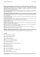
RTM Elster AMCO applicative PFS Coronis Systems In this example the request to configure alarm windows activation is done between 8:01AM and 8:59AM. 8AM 9AM 10AM 11AM RTM RTC Time allowed for alarm frame 5.12.3. Automatic configuration of the destination route (via SDP) RTM Elster AMCO integrates the CORONIS SDP feature “Self Discovery Protocol” used to identify the path to reach the root of the network. RTM Elster AMCO uses this parameter to transmit its alarm frames.
RTM Elster AMCO applicative PFS Coronis Systems 5.12.5.Triggering an alarm frame Automatic transmission alarm frame format Applicative Command Generic header Alarm Status RTC on Alarm detection Alarm Data field 1 byte 23 bytes 3 bytes 7 bytes 2 bytes 0x40 ATTENTION: an alarm frame only has one type of detection. When several alarms are detected, RTM Elster AMCO emits the frames one after the other. Next alarm frame will be transmitted after the previous frame has been acknowledged.
RTM Elster AMCO applicative PFS Coronis Systems Alarm Status for RTM Elster AMCO encoder profile Alarm Status MSB Byte Bit Number Bit 23 (MSB) Bit 22 Bit 21 Bit 20 Bit 19 Bit 18 Bit17 Bit 16 (LSB) Bit Definition Not used Not used Not used Not used Not used Not used Not used Not used Alarm Status Middle Byte Bit Number Bit Definition Bit 15 (MSB) bit 14 bit 13 bit 12 Not used Back flow detection on Port B Back flow detection on Port A Encoder reading error detection on Port B
RTM Elster AMCO applicative PFS Coronis Systems 5.12.6.alarm frame acknowledgment The remote device must send an acknowledgment frame (command 0xC0) to confirm reception of the alarm frame and end dialog. Acknowledge request data format Applicative command Alarm Status 1 byte 3 bytes 0xC0 Same as received in the alarm frame If the RTM Elster AMCO does not receive this acknowledgment, it re-transmits the alarm frame several time, with a delay between each retransmission.
RTM Elster AMCO applicative PFS Coronis Systems 6.Radio address description Each Coronis product has its own radio address in order to achieve bidirectional communications. A bar code label is applied to each product, indicating the RTM Elster AMCO radio address.
RTM Elster AMCO applicative PFS Coronis Systems 7.
RTM Elster AMCO applicative PFS Param ID Coronis Systems Size in bytes Description Access Right (Pulse register) Access Right (encoder register) Default value (Hexa) Restriction on parameters Encoder Unit & Model parameters 0x1D Encoder Model on Port A (encoder only) 2 - R 0xFFFF 0x1E Encoder Model on Port B (encoder only) 2 - R 0xFFFF 0x1F Encoder Unit on Port A (encoder only) 2 - R 0xFFFF 0x20 Encoder Unit on Port B (encoder only) 2 - R 0xFFFF Leakage detection function 0x
RTM Elster AMCO applicative PFS Param ID Coronis Systems Size in bytes Description Access Right (Pulse register) Access Right (encoder register) Default value (Hexa) Restriction on parameters Back flow detection function (encoder only) 0x3E Back flow detection date on Port A 7 - R 0x01010101010101 An erroneous RTC Format will be rejected 0x3F Back flow detection date on Port B 7 - R 0x01010101010101 An erroneous RTC Format will be rejected 0x40 Back flow detection period on Port A ex
RTM Elster AMCO applicative PFS Param ID Coronis Systems Size in bytes Description Access Right (Pulse register) Access Right (encoder register) Default value (Hexa) Restriction on parameters Battery life 0x50 Battery life duration counter 3 R R TBD by CORONIS - 0x51 Date end of battery life detection 7 R R 0x01010101010101 An erroneous date must be rejected Configuration of alarm 0x57 Alarm Window configuration parameter 1 R/W R/W 0x00 See Section §xxx 0x58 Alarm Configuratio
RTM Elster AMCO applicative PFS Coronis Systems 8.
RTM Elster AMCO applicative PFS Coronis Systems 9.APPENDIX C : SERVICE COMMANDS Services commands are used to configure Wavecard modules or to read radio parameters independently of the connected host equipment. No data sent to the connected host when a Wavecard recognizes a service command. These commands are mainly used to handle: • Link budgets with remote modules (RSSI levels) • Verifying products firmware version remotely • Setting or reading parameters via RF (not described here) 9.1.
RTM Elster AMCO applicative PFS Coronis Systems 9.3.Request types The transmitting module sends a service command that includes a request type. Each request type has an associated response type which is included in the SERVICE_RESPONSE command. In command byte coding, response frames reuse the request command with the LSB bit set to 1. • Request type REQUEST TYPE NAME VALUE DESCRIPTION PARAMETER(S) GET_TYPE 0x20 Command used to read equipment type and RSSI level from remote equipment.