
User Manual
MODE "B":
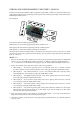
1. Power on the programming card, connect the S.BUS decoder to the- programming interface, switch to "B" By
left or right key click of SW2. Push down the middle button of SW2 to link the decoder. If LED2 - LED4
display "-","-","-" indicate а successful link. If have no display, please link decoder again.
2. After а, successful link left or right key click of SW2 to change the physical port item.
Port “1”: LED2 - LED4 display the servo channel number of port 1. All number of servo channel (1 - 18: CH1
- CH16, DG1 and DG2) can be programmed. Left or right key click of SW1 to change the servo channel number.
Servo writing by pushing the middle button of SW1.
Port “2”: LED2 - LED4 display the servo channel number of port 2. All number of servo channel (1 - 18: CH1
- CH16, DG1 and DG2) can be programmed. Left or right key click of SW1 to change the servo channel number.
Servo writing by pushing the middle button of SW1.
Port “3”: LED2 - LED4 display the servo channel number of port 3. All number of servo channel (1 - 18: CH1
- CH16, DG1 and DG2) can be programmed. Left or right key click of SW1 to change the servo channel number.
Servo writing by pushing the middle button of SW1.
3. After write operation, you should repower on the programming card and link the decoder to check all
parameters you have wrote.
MODE "С":
1. Connect the Li-Po battery package to the battery test port of the programming card at right pin order. “G”
indicates the negative electrode of the lowest cell. Left or right key click of SW2 to select mode “С”, push
down the middle button of SW2 and enter the battery voltage test mode.
2. LED1 display the cell number of the battery package, LED2 - LED4 indicate the voltage value of the current
cell.
3. "t" indicate the total voltage of the battery package.