
User's Manual


Overview
4 Voasis™ UMTS/DCS/PCS Installation and Configuration Manual
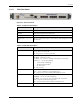
1.2.1.2 VCU Rear Panel
The VCU DC power connection is located at the VCU rear panel.
Figure
1-3. VCU Rear Panel
1.2.2 Voasis™ Access Pod (VAP)
Each VAP functions as antenna – transmitting and receiving RF service signals. Every VAP is
connected to an RJ-45 jack via the RJ45 connector on the VAP underside.
Note: The VAP is connected to spare Ethernet jacks that are not already in use in the Ethernet
network.
The VAP can be mounted/hanged on the wall or placed on a flat surface (such as a desk).
The following figure shows the desktop VAP and the underside view with the CAT-5/6 patch-cord
cable.
Figure
1-4. Voasis™ Access Pod
VAP LED Indicators:
Table
1-3: VAP LEDs
LED Description
PWR Solid Green - Power supplied to VAP
Off - No power supplied to VAP
ACT
Status of VAP (Blue)
Solid – power supplied to VAP, normal operation.
Fast Blink – user activated ‘Access Pod Identify’ on this AP.
Slow Blink – power supplied to VAP, unit initializing.
Off – power not supplied to Access Pod or Access Pod is faulty.
90-264V AC, 47-63 Hz
250W (fully loaded)