
User's Manual


Overview
Voasis™ UMTS/DCS/PCS Installation and Configuration Manual 3
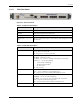
1.2.1.1 VCU Front Panel
Figure
1-2. VCU Front Panel
Table
1-1: VCU Ports Description
Ports Description
BTS In/Out RF connections to the service provider equipment
Console RS232 local management connection
Management RJ45 WEB management connection
(V)AP Ports 1-4, 5-8,
9-12
VAP port connections. RJ-45 connection to VAP through the LAN
infrastructure
Table
1-2: VCU LEDs Description
LED Description
System PWR
VCU power LED (Green):
Green - Power to VCU is OK
Off - No power is received by the VCU
System ACT
System activity LED (Green):
Slow Blink – Normal operation
Fast Blink – user activated ‘Control Unit Identify’ on this VCU.
Solid Green - one of the following:
- Control Unit is initializing
- No RF signal from BTS
- Service is off
Off - VCU is faulty.
AP PWR
Access Pod Power indication (Green)
Green – power supplied to corresponding port.
Off – no power (to corresponding VAP) supplied to port.
AP ACT
Status of corresponding VAP (Green).
Slow Blink - associated VAP is initializing
Fast Blink – user activated ‘Access Pod Identify’ on this AP.
Solid - associated VAP normal operation.
Off – associated Access Pod is faulty or disconnected.
Reset Reset