
User's Manual
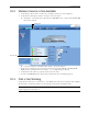
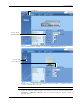
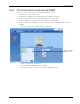

Table Of Contents
- Preface Material
- Policy for Warrantee and Repair
- General Warranty
- Specific Product Warranty Instructions
- Returns
- Limitations of Liabilities
- Reporting Defects
- Safety Warnings
- Compliance with RF Safety Requirements
- Certification and Compliance to Standards
- About This Guide
- List of Acronyms
- Table of Contents
- 1 Overview
- 2 Installation Workflow
- 3 Infrastructure Requirements and Layout Planning
- 4 VCU Unit Installation and Provisioning
- 5 VAP Installation and Provisioning
- 6 Navigating the Web Access Application
- 7 VCU Monitoring and Configuration
- 8 VAP Monitoring and Configuration
- 9 Administrative Operations
- 10 Troubleshooting
- Appendix A - Traps
- Appendix B – MobileAccess VE MIB Tree Structure (Version 1.8)

Troubleshooting
Mixed Band LTE 700 MHz MobileAccessVE Instant Coverage Solution User Manual 73
• Select the VAP from the topology tree and click the RF Parameters sub-tab.
• Confirm that the VCU port is functioning (VAP status LED - top LED in VAP icon
associated with this Pod is green).
Note: The
Activity
LED on the actual VAP is BLUE.
• Verify the VAP was NOT configured by mistake to use the
internal
antennas (See
Channel 1/ Channel 2 Antenna parameter in RF Parameters sub-tab, shown in
previous figure).
Selected VAP
Config tab
Service Mode
(MIMO/SISO)
Service RF tab