
User's Manual
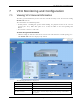
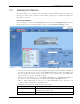
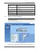

Table Of Contents
- Preface Material
- Policy for Warrantee and Repair
- General Warranty
- Specific Product Warranty Instructions
- Returns
- Limitations of Liabilities
- Reporting Defects
- Safety Warnings
- Compliance with RF Safety Requirements
- Certification and Compliance to Standards
- About This Guide
- List of Acronyms
- Table of Contents
- 1 Overview
- 2 Installation Workflow
- 3 Infrastructure Requirements and Layout Planning
- 4 VCU Unit Installation and Provisioning
- 5 VAP Installation and Provisioning
- 6 Navigating the Web Access Application
- 7 VCU Monitoring and Configuration
- 8 VAP Monitoring and Configuration
- 9 Administrative Operations
- 10 Troubleshooting
- Appendix A - Traps
- Appendix B – MobileAccess VE MIB Tree Structure (Version 1.8)

VAP Monitoring and Configuration
Mixed Band LTE 700 MHz MobileAccessVE Instant Coverage Solution User Manual 59
The following table provides a description of the displayed VAP RF parameters for each service.
Parameter Description
Type Set (Read Only) according to unit type (LTE)
Service Control Enables (On)/Disables (Off) the service
DL Pout Level
Level of from BS side.
Normal = output power will be at required (normal) level
Low = output power will be attenuated by 5 dB less than the
required level. This option can be used for smaller coverage areas
that do not require the full power of the VAP for coverage.
DL Pout
Measured output power. Normal output power is approximately
14dBm.
Antenna Antenna type: Internal/External/All Antennas (default)
Note: VAP RF settings (Service Mode, DL Pout Level, Antenna) are saved in the VCU associated
to the port to which the VAP is connected, such that in case you replace a VAP all parameters
are automatically set to the new VAP. In case you do not want to keep the configuration of the
replaced VAP, remove it from the topology baseline before connecting the new VAP.