
User's Manual
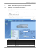
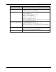
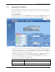
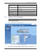

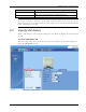
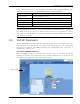
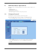
Table Of Contents
- Preface Material
- Policy for Warrantee and Repair
- General Warranty
- Specific Product Warranty Instructions
- Returns
- Limitations of Liabilities
- Reporting Defects
- Safety Warnings
- Compliance with RF Safety Requirements
- Certification and Compliance to Standards
- About This Guide
- List of Acronyms
- Table of Contents
- 1 Overview
- 2 Installation Workflow
- 3 Infrastructure Requirements and Layout Planning
- 4 VCU Unit Installation and Provisioning
- 5 VAP Installation and Provisioning
- 6 Navigating the Web Access Application
- 7 VCU Monitoring and Configuration
- 8 VAP Monitoring and Configuration
- 9 Administrative Operations
- 10 Troubleshooting
- Appendix A - Traps
- Appendix B – MobileAccess VE MIB Tree Structure (Version 1.8)

VCU Monitoring and Configuration
Mixed Band LTE 700 MHz MobileAccessVE Instant Coverage Solution User Manual 55
dedicated tab (Service1 RF and Service2 RF) and can be individually configured. For example, if
the selected Product Type in the Module Info tab is LOWER A,B,C – UPPER C, each one of the
SISO channels will be displayed in a separate tab. If the MIMO LOWER A,B,C-LOWER A,B,C
product type is selected, each MIMO channel is also displayed in a separate tab and can be
individually configured and viewed.
The following table provides a description of the RF parameters displayed in the Service RF tabs.
Parameter
Description
Type Set (read only) according to unit type (LTE Upper C or Lower B,C
– depending on model)
BTS Connection Type of BTS RF connection (Simplex/Duplex). Default = duplex.
DL CF* Set (read only) Center frequency (from BTS) according to LTE
700MHz range - (Upper C Block or Lower A, B, C Blocks). The CF
is the same for both UL and DL signals.
Max Exp DL Pin* Maximum expected input power from the BTS. Used for
adjustment procedure. Range: 0-33 dBm. User defined.
DL Pin
Actual measured Power input (read only). In SISO mode only
Channel 1 Pin is relevant.
UL System Gain Used for adjusting the UL system gain. Range: -15 dB to +5 dB
Service Control
Enables (On)/Disables (Off) the service
* Required parameters to be provisioned by the user.