
User's Manual
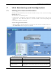
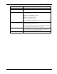
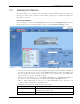
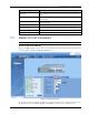
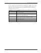

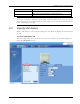
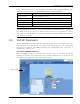
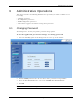
Table Of Contents
- Preface Material
- Policy for Warrantee and Repair
- General Warranty
- Specific Product Warranty Instructions
- Returns
- Limitations of Liabilities
- Reporting Defects
- Safety Warnings
- Compliance with RF Safety Requirements
- Certification and Compliance to Standards
- About This Guide
- List of Acronyms
- Table of Contents
- 1 Overview
- 2 Installation Workflow
- 3 Infrastructure Requirements and Layout Planning
- 4 VCU Unit Installation and Provisioning
- 5 VAP Installation and Provisioning
- 6 Navigating the Web Access Application
- 7 VCU Monitoring and Configuration
- 8 VAP Monitoring and Configuration
- 9 Administrative Operations
- 10 Troubleshooting
- Appendix A - Traps
- Appendix B – MobileAccess VE MIB Tree Structure (Version 1.8)

VCU Monitoring and Configuration
Mixed Band LTE 700 MHz MobileAccessVE Instant Coverage Solution User Manual 54
Alarm Description
Mismatch
Red – Mismatch of services (e.g. between VCU and connected
VAPs).
Service 1/2 RF DL Pwr Low
RED - DL RF Power is lower by 15dBm (or more) from the Max
Expected Pin.
Service 1/2 RF DL Pwr High
RED - the input power exceeds the maximum expected Pin by
more than 3 dB.
Service Off User has disabled the service.
VCUs in Baseline RED – Communication lost with VCU defined in baseline
VAPs in Baseline RED - Communication lost with VAP defined in baseline
Overall Status Indicates Fault (RED) level or GREEN if there are no faults.
7.3 Master VCU RF Parameters
Note: The RF parameters are not displayed for control units functioning as Slave VCUs.
To access the Service RF tab
Click the Config tab from the main menu bar and then select the Master control unit from the
network topology and click the RF Parameters tab.
Figure 7-1: VCU Service RF Tab
The parameters displayed in Service RF tabs correspond to the services configuration selected in
the Module Info tab. Each MIMO (MIMO1 and MIMO2) and SISO service is displayed in a