
User's Manual
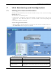
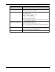
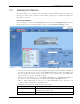
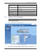
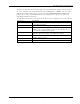

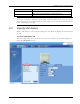
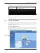
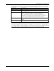
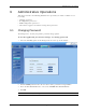
Table Of Contents
- Preface Material
- Policy for Warrantee and Repair
- General Warranty
- Specific Product Warranty Instructions
- Returns
- Limitations of Liabilities
- Reporting Defects
- Safety Warnings
- Compliance with RF Safety Requirements
- Certification and Compliance to Standards
- About This Guide
- List of Acronyms
- Table of Contents
- 1 Overview
- 2 Installation Workflow
- 3 Infrastructure Requirements and Layout Planning
- 4 VCU Unit Installation and Provisioning
- 5 VAP Installation and Provisioning
- 6 Navigating the Web Access Application
- 7 VCU Monitoring and Configuration
- 8 VAP Monitoring and Configuration
- 9 Administrative Operations
- 10 Troubleshooting
- Appendix A - Traps
- Appendix B – MobileAccess VE MIB Tree Structure (Version 1.8)

VCU Monitoring and Configuration
Mixed Band LTE 700 MHz MobileAccessVE Instant Coverage Solution User Manual 53
7.2 Viewing VCU Alarms
The alarms displayed in the Alarms tab correspond to the VCU (Master/Slave) selected in the
topology tree. When a VCU element is selected in the topology tree, the Alarm tab displays the
main alarms in the unit.
To view VCU Alarms
In the Topology Tree select the Control Unit (VCU) then click the Config(uration) tab in the
menu bar located at the top of the window. Refer to the VCU Alarms and Mask sub tab.
• If one or more alarms occur, the corresponding Status indicator will be illuminated in RED. If
the VCU is OK and no fault occurs, the Overall Status indicator will show GREEN. The
displayed VCU alarms include general status alarms (e.g. Over Temperature, VCU Faulty) and
service specific (e.g. Service 1/2 DL RF Pwr Low).
• When the selected product type is set for MIMO configuration (e.g. LWR ABC-LWR ABC) then
the “Service1” and “Service2” alarms correspond to the MIMO1 and MIMO2 services.
• When a SISO configuration is selected (e.g. LWR ABC-UPPER C), the “Service1” and
“Service2” alarms correspond to each SISO service.
The following table provides a description of the VCU alarms.
Alarm Description
VCU Faulty
RED - VCU fault. Remove and re-apply power to VCU. If
problem persists, replace VCU.
Over Temperature Temperature of unit exceeds normal range.
Product Type