
User's Manual
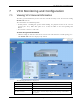
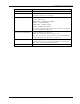
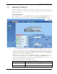
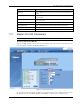

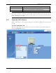
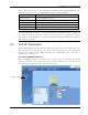
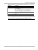
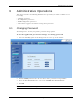
Table Of Contents
- Preface Material
- Policy for Warrantee and Repair
- General Warranty
- Specific Product Warranty Instructions
- Returns
- Limitations of Liabilities
- Reporting Defects
- Safety Warnings
- Compliance with RF Safety Requirements
- Certification and Compliance to Standards
- About This Guide
- List of Acronyms
- Table of Contents
- 1 Overview
- 2 Installation Workflow
- 3 Infrastructure Requirements and Layout Planning
- 4 VCU Unit Installation and Provisioning
- 5 VAP Installation and Provisioning
- 6 Navigating the Web Access Application
- 7 VCU Monitoring and Configuration
- 8 VAP Monitoring and Configuration
- 9 Administrative Operations
- 10 Troubleshooting
- Appendix A - Traps
- Appendix B – MobileAccess VE MIB Tree Structure (Version 1.8)

VCU Monitoring and Configuration
Mixed Band LTE 700 MHz MobileAccessVE Instant Coverage Solution User Manual 52
Field
Description
SW Inactive Version Version of other system SW version not in use
Uplink Cable Comp.
When enabled, used to minimize interference that may be caused
by bonded cables that vary in length
Product Type
Provides options for selecting two channels in MIMO or SISO
service configurations:
LOWER A,B,C – LOWER A,B,C (MIMO)
UPPER C – UPPER C (MIMO)
LOWER A,B,C – UPPER C (SISO)
UPPER C - LOWER A,B,C (SISO)
Note: Each of the channels is displayed in a dedicated Service RF
tab and is individually configured.
Antenna Type Modify Button Enables defining the antenna type:
All internal/external) for all of the VAPs at once.
Note: The antenna type can be defined for each VAP individually
via the VAP GUI (Service RF tab-see section
8.3).
Identify (ON/OFF)
Enabling this option enables finding the physical location of the
selected element (See 10.1). When this option is set to ON, the
LEDs on the corresponding VAP/VCU flickers.
Restart VCU Button SW reset of the unit