
User's Manual
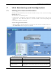
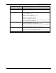
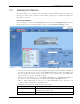
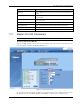

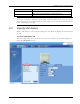
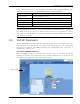
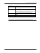
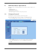
Table Of Contents
- Preface Material
- Policy for Warrantee and Repair
- General Warranty
- Specific Product Warranty Instructions
- Returns
- Limitations of Liabilities
- Reporting Defects
- Safety Warnings
- Compliance with RF Safety Requirements
- Certification and Compliance to Standards
- About This Guide
- List of Acronyms
- Table of Contents
- 1 Overview
- 2 Installation Workflow
- 3 Infrastructure Requirements and Layout Planning
- 4 VCU Unit Installation and Provisioning
- 5 VAP Installation and Provisioning
- 6 Navigating the Web Access Application
- 7 VCU Monitoring and Configuration
- 8 VAP Monitoring and Configuration
- 9 Administrative Operations
- 10 Troubleshooting
- Appendix A - Traps
- Appendix B – MobileAccess VE MIB Tree Structure (Version 1.8)

VCU Monitoring and Configuration
Mixed Band LTE 700 MHz MobileAccessVE Instant Coverage Solution User Manual 51
7 VCU Monitoring and Configuration
7.1 Viewing VCU General Information
The VCUs general information (such as unit name and SW versions) can be viewed in the Config
Module Info sub-tab.
The tab includes two additional options:
• Identify button - Enabling this option enables finding the physical location of the selected
element (See
10.1). When this option is set to ON, the LEDs on the corresponding VCU
flickers.
• Reset button - SW reset of the unit
To view VCU general information
• Click the Config tab from the main menu and select the VCU from the network topology tree.
The Module Info sub-tab is displayed by default.
The following information is displayed:
Field
Description
Name User defined name for system element (up to 17 characters)
Serial Number Factory set ID number
Product Revision Revision number of VCU/VAP
SW Active Version
Version of the SW currently being used to manage and monitor
the system