
User's Manual
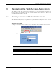
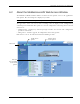
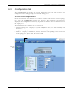
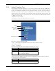
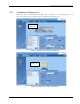
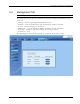
Table Of Contents
- Preface Material
- Policy for Warrantee and Repair
- General Warranty
- Specific Product Warranty Instructions
- Returns
- Limitations of Liabilities
- Reporting Defects
- Safety Warnings
- Compliance with RF Safety Requirements
- Certification and Compliance to Standards
- About This Guide
- List of Acronyms
- Table of Contents
- 1 Overview
- 2 Installation Workflow
- 3 Infrastructure Requirements and Layout Planning
- 4 VCU Unit Installation and Provisioning
- 5 VAP Installation and Provisioning
- 6 Navigating the Web Access Application
- 7 VCU Monitoring and Configuration
- 8 VAP Monitoring and Configuration
- 9 Administrative Operations
- 10 Troubleshooting
- Appendix A - Traps
- Appendix B – MobileAccess VE MIB Tree Structure (Version 1.8)

Navigating the Web Access Application
Mixed Band LTE 700 MHz MobileAccessVE Instant Coverage Solution User Manual 47
6.3.1 Network Topology Tree
The Configuration Network Topology Tree appears on the left hand side when the Config tab is
selected. Connected Slave VCUs and VAPs are automatically detected and displayed in the
topology. The MobileAccessVE Web Access Application includes a Baseline feature providing an
indication on network elements (VCUs or VAPs) which were disconnected from the VE network.
Connected Slave VCUs, and VAPs are automatically added to the Baseline upon detection, and
will appear in the topology as grayed out in case they get disconnected. The network elements
are displayed in two levels:
• First Level – up to 12 VCUs
• Second Level – Up to 12 VAPs connected to each VCU
Note: The root is MobileAccessVE.
Each unit is assigned a Type Px-name:
• Type – VCU-M, VCU or VAP (for Master VCU, Slave VCU or VE Access Pod)
• Px - VCU port number
• Name – user defined
Each unit is displayed with a colored bullet that indicates its’ status:
Color
Indicates
Green OK
Red Alarm Condition
Gray
Disconnected unit (e.g. faulty connection)
Generates RED Baseline alarm in Alarms tab
(see Viewing VCU Alarms).
The root (the entire MobileAccessVE site) is also associated with a colored bullet that indicates
the overall status of the deployment:
Color
Indicates
Green
OK
Red
Alarm Condition in one or more VCUs or VAPs
Root
Master VCU –
first level
VAP – second
Disconnected unit