
User's Manual
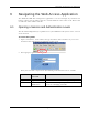
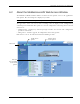
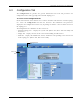
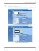
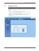
Table Of Contents
- Preface Material
- Policy for Warrantee and Repair
- General Warranty
- Specific Product Warranty Instructions
- Returns
- Limitations of Liabilities
- Reporting Defects
- Safety Warnings
- Compliance with RF Safety Requirements
- Certification and Compliance to Standards
- About This Guide
- List of Acronyms
- Table of Contents
- 1 Overview
- 2 Installation Workflow
- 3 Infrastructure Requirements and Layout Planning
- 4 VCU Unit Installation and Provisioning
- 5 VAP Installation and Provisioning
- 6 Navigating the Web Access Application
- 7 VCU Monitoring and Configuration
- 8 VAP Monitoring and Configuration
- 9 Administrative Operations
- 10 Troubleshooting
- Appendix A - Traps
- Appendix B – MobileAccess VE MIB Tree Structure (Version 1.8)

Navigating the Web Access Application
Mixed Band LTE 700 MHz MobileAccessVE Instant Coverage Solution User Manual 46
6.3 Configuration Tab
The Configuration tab provides the general information and service RF parameters for
configuration of the units appearing in the Network Topology tree.
To access a VCU Configuration tab
On the left hand side of the window select a Master VCU/Slave VCU from the network topology
tree. Select the Configuration tab from the menu-bar. The information and parameters
displayed in the Configuration sub-tabs vary depending on whether a VCU or VAP is selected in
the topology tree.
The Configuration tab is divided in to three main areas:
• Network Topology Tree – Displays the system units (Master VCU, Slave VCUs and VAPs) and
their status
• Display Area – Displays the icon of the selected unit including the LED statuses
• Work Area – Displays the Module Info, alarms, and RF tabs corresponding to the unit selected
in the topology tree (Master VCU, Slave VCU or VAP)
Selected
VCU
Configuration
tab