
User's Manual
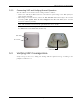
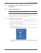
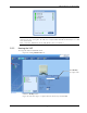
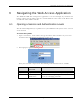
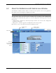
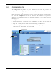
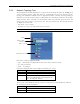
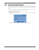
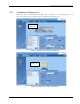
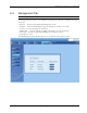
Table Of Contents
- Preface Material
- Policy for Warrantee and Repair
- General Warranty
- Specific Product Warranty Instructions
- Returns
- Limitations of Liabilities
- Reporting Defects
- Safety Warnings
- Compliance with RF Safety Requirements
- Certification and Compliance to Standards
- About This Guide
- List of Acronyms
- Table of Contents
- 1 Overview
- 2 Installation Workflow
- 3 Infrastructure Requirements and Layout Planning
- 4 VCU Unit Installation and Provisioning
- 5 VAP Installation and Provisioning
- 6 Navigating the Web Access Application
- 7 VCU Monitoring and Configuration
- 8 VAP Monitoring and Configuration
- 9 Administrative Operations
- 10 Troubleshooting
- Appendix A - Traps
- Appendix B – MobileAccess VE MIB Tree Structure (Version 1.8)

VAP Installation and Provisioning
Mixed Band LTE 700 MHz MobileAccessVE Instant Coverage Solution User Manual 42
5.4 Naming the VAPs, Verifying Connections and
Monitoring
5.5 Provisioning the VAPs
Note: This section provides only the information required for provisioning the VAPs. For a full
description of the VAP configuration options, refer to Chapter
8 .
The VAPs are auto-discovered by the VCU and can be monitored via a remote or a local
connection (to the Master VCU). The VAPs are auto-configured by the VCU without user
intervention (no configuration procedure is required). However, if you wish, you may assign
each VAP an identifiable name corresponding to its physical location.
5.5.1 Verifying Normal VAP Operation
Use the RF Parameters and Module Info sub-tabs to review the VAP information and status.
1. If a session in not already open to the MobileAccessVE Web GUI application, open a session
to the Master VCU according to section
4.4.2.
2. Select a VAP from the Network Topology Tree.
Each VAP has a default name showing the number of the Slave VCU port to which the VAP is
connected.
3. To verify normal operation of the VAP:
• In the Network Topology Tree, under the Control Unit, verify that an LED is displayed
(either RED or GREEN) for each connected VAP.
• If the VAP LED is RED, select the VAP from the network topology tree then select the
Config tab. Refer to the Alarms tab work area. Use the displayed alarms to identify the
problems.